


0010577
506
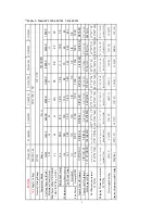
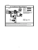
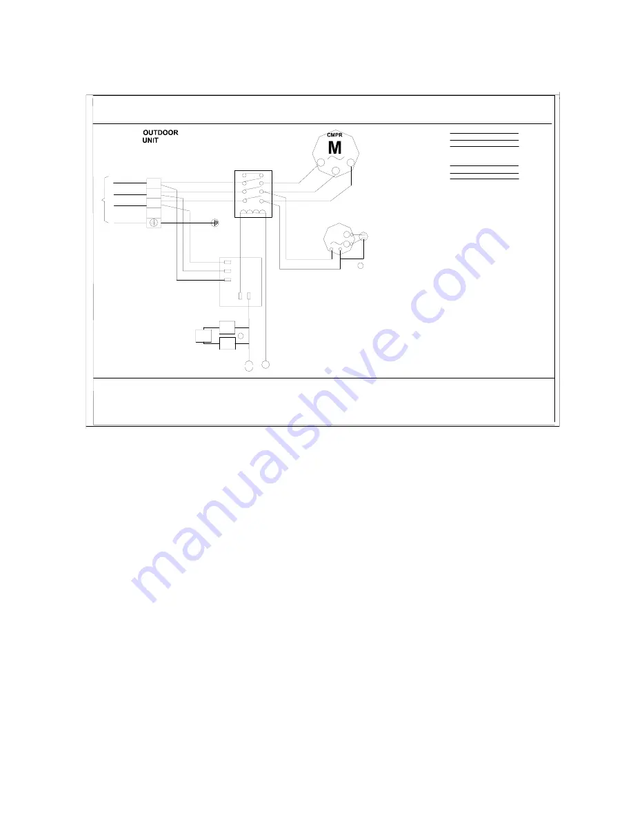
Air Conditioner Wiring Diagram
Y
C
GND
60Hz 3N
~
208/230V
YL
CN-T
CN-R
CN-S
L2
U
V
W
4
CC
Optional
Low & High
Pressure
Switches
and Vent
temperature
sensor
S
BR
BK
M
BR
R
OFM
COLOR CODES
BK - BLACK BL - BLUE GY - GRAY
BR - BROWN GR- GREEN OR - ORANGE
PU - PURPLE RD - RED VI - VIOLET
WH - WHITE YL - YELLOW
USE COPPER CONDUCTORS ONLY
WARNING CABINET MUST BE PERMANENTLY GROUNDED
AND ALL WIRING TO CONFORM TO I.E.C.,N.E.C.,C.E.C.,
C.L.C. AND LOCAL CODES AS APPLICABLE.
REPLACEMENT WIRE MUST BE THE SAME GAGE AND
INSULATION TYPE AS ORIGINAL WIRE.
LINE VOLTAGE
FACTORY STANDARD
FIELD INSTALLED
OPTIONAL
LOW VOLTAGE
FACTORY STANDARD
FIELD INSTALLED
OPTIONAL
L1
L3
L1 L2 L3
1) Confirm system selection. Optional components may be field or factory installed.
2) If LPS and/or HPS and/or VTS not installed or removed, a jumper wire must be present across circuit for system to operate.
3) For proper system operation, consult indoor unit and outdoor unit installation instructions to confirm system match up and blower speed selection.
4) Optional OFM components may connect capacitor common and motor common, for reciprocating compressor there may have crankcase heater
consult outdoor unit installation instructions for details.If OFM only have one capacitor wire,connect Com wire to capacitor.
L
1
L2
L3
N
PU
PU
BK
YL
RD
BK
YL
RD
RD
YL
BK
CN-COM
CN-NO
YL
BL
BK
VTS
YL
HPS
YL
2
LPS
BL
YL/GR
13
V1160C3H
Summary of Contents for V1124C2H
Page 17: ...Made in P R C...


