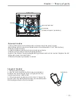
Inlet Valve
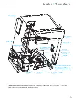
Theory of parts
-
>
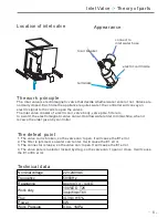
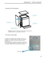
3. Top panel
4. Left side panel
1. Baseboard
2. Left baseboard
5. Middle rear
crosspiece
Inlet valve
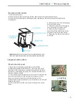
Access inlet valve
1. Disconnect power.
2. Remove the water inlet hose. (Note : Be careful of remain water drop.)
3. Remove the baseboard, left baseboard, top panel, left side panel and middle rear
crosspiece.
4. Disconnect the 2 terminal lugs
from the inlet valve.
5. Push the valve from the lower
rear crosspiece to take it off.
6. Remove the clamp and
disconnect the inlet hose (to air
breaker) from the water valve.
7. Reverse the above procedure
to install.
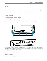
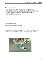
1.Open the control panel and take out the PCB;
2.Unplug the CON3 and P4 wires , then use the multi-
meter Ω shelf to measure resistance between the blue
wire (EV1) and white wire (IS), the normal resistance is
about 3.4KΩ to 4.3KΩ.
3. I f the measured resistance is not correct, it means the
valve coil is broken or the connector is loose. In this
case, we should check the connection first. If the
problem hasn’t been solved by re-connection, we should
replace the valve..
4.If the resistance is OK, we need to inspect the valve
body.
Inspect inlet valve
unplug
Check electric part
Attention:
Build in models have no Baseboard and
left and right baseboard, but adjustable baseboard.
-
9 -
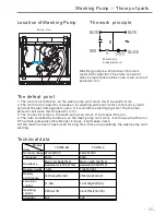
IS
EV1
Summary of Contents for WQP12-B9227E
Page 34: ...Troubleshooting 34 ...
Page 35: ...Troubleshooting 35 ...
Page 36: ...Troubleshooting 36 ...
Page 37: ...Troubleshooting 37 ...
Page 38: ...Troubleshooting 38 ...


