Page 22
•
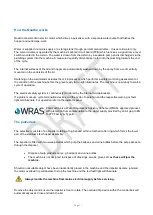
Ensure that the machine connection complies with statutory regulations, local water authority bylaws and
relevant codes of practice.
A dedicated isolation valve (not supplied), must be fitted in the cold water supply pipework. It
should be placed close to the machine so that it is readily accessible during maintenance or
servicing
•
A feed hose is required for connecting the machine to the water supply.
•
The cistern is fitted to this machine and provided with an ‘EN 13077, Family A, Type B’ to prevent back
syphon of contaminated water.
Under no circumstances may the cistern be bypassed
Waste outlet connection
Quattro is designed to be installed to 50mm pipework with a fall of 1:25 or sufficient to maintain
a self-cleansing velocity
We recommend that the maximum total length of pipework before entering the 10mm vertical
soil stack is 3m with one swept bend. If an additional swept bend is introduced then the
maximum length would reduce to 2.5m
•
Minimum size of waste pipe 50mm.
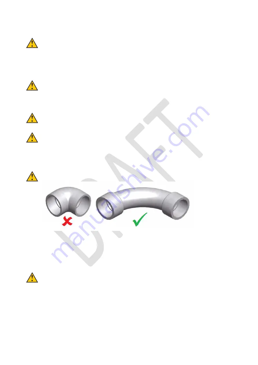
Connect the machine to the drain using the minimum number of long radius/swept bends. Use
long radius or ‘swept’ bends - never short bends or 90° elbows:
•
When a machine is installed on an existing drain then check that there is no calcium build-up as this
reduces the efficiency of the drain and may lead to blockages.
•
Provide easy access for rodding.
•
The machine is fitted with a 50mm ‘P’ trap inside the cabinet terminating in a compression fitting suitable for
a 50mm pipe stub. The outlet is for rear connection. Fitting a slow bend will allow for alternative connections
through the floor / to the right / and to the left.
Never connect waste outlet to a septic tank
•
Machine waste must be run separately to a 100mm vertical soil stack.
•
Ensure the waste takes the shortest route to the soil stack.
•
Ensure a clean run inside pipework - no burrs or reducing shoulders.
•
Support plastic pipework adequately on runs to prevent sagging. Remember ceiling voids can get very
warm.
•
Avoid running the drain line near or across hot water pipes.
Summary of Contents for Quattro Vanguard Original
Page 1: ...Page 1...
Page 2: ...Page 2...
Page 3: ...Page 3...
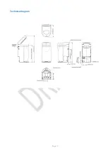
Page 12: ...Page 12 Technical diagram...
Page 17: ...Page 17 1...
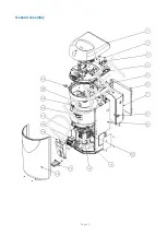
Page 32: ...Page 32 General assembly...
Page 37: ...Page 37 Main pump removal diagram 3...
Page 38: ...Page 38 Mechanical assembly removal diagram 3 4 5 6...
Page 40: ...Page 40 Plumbing diagram...
Page 43: ...Page 43 Wiring diagram single phase 1 PHASE MOTOR 120 VOLTS 1 PHASE PUMP MOTOR 120 VOLTS...
Page 49: ...Page 49...


