
31
HAIKU® BY BIG ASS FANS
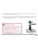
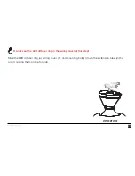
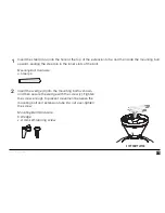
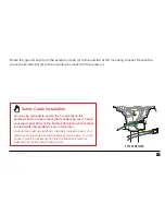
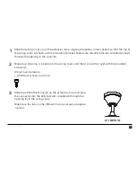
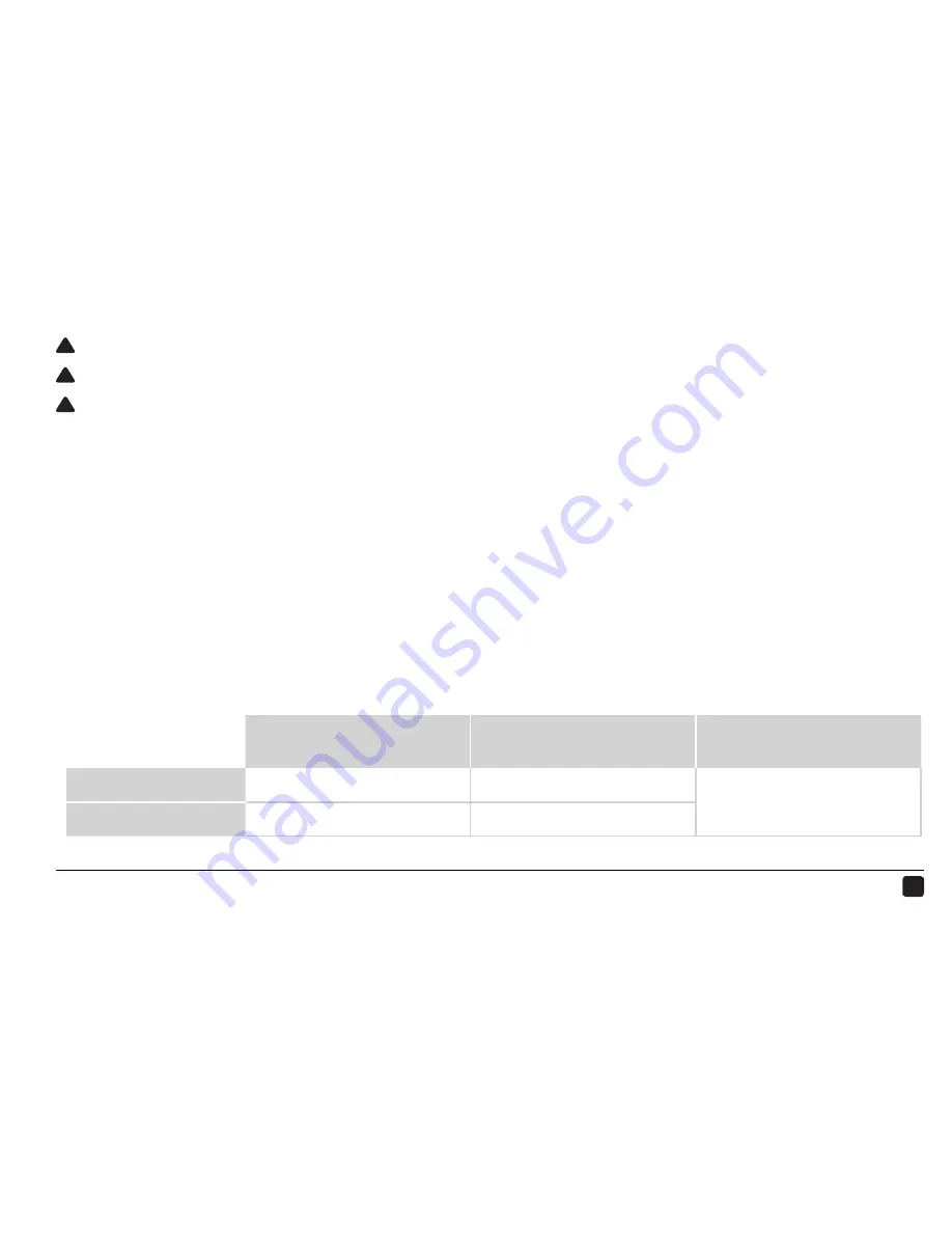
Make sure power is disconnected before wiring the fan!
If required by your local electrical code, a licensed electrician must install the fan.
Do not connect the fan to a damaged power source! Do not attempt to resolve electrical failures on
your own. Consult a qualified electrician if uncertain of the electrical installation of this fan.
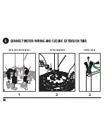
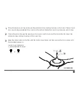
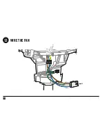
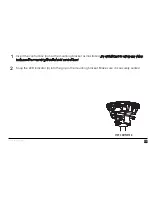
Make the electrical connections by securing the supply power wires to the loose ends of the wiring
harness (
a
) with the provided wire nuts or a terminal strip (or the means of connection required by
your local electrical code).
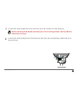
Test the connection by lightly tugging on the wires.
Tuck the power wiring into the outlet box or building structure.
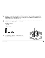
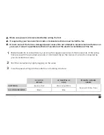
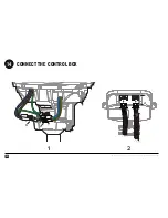
AC HOT/L1
BROWN
AC NEUTRAL/L2
BLUE
PE/EARTH GROUND
GREEN
AUSTRALIA
Brown or Red
Black or Light Blue
Green with Yellow Tracer
ALL OTHER REGIONS
Brown
Blue
!
!
!
3
2
1
Summary of Contents for FR127C-U1EXX
Page 1: ...INSTALLATION GUIDE INSTALLATION GUIDE ...
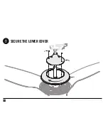
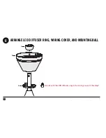
Page 22: ...20 REV F 06 08 2018 2015 BIG ASS FANS ALL RIGHTS RESERVED SECURE THE LOWER COVER c 7 b a ...
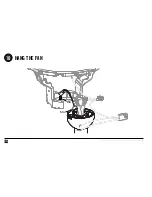
Page 28: ...26 REV F 06 08 2018 2015 BIG ASS FANS ALL RIGHTS RESERVED HANG THE FAN 10 Slot Rib ...
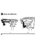
Page 34: ...32 REV F 06 08 2018 2015 BIG ASS FANS ALL RIGHTS RESERVED INSTALL THE CONTROL BOX 13 a 1 2 b ...
Page 42: ...NOTES ...
Page 44: ...HKU INST 74 ENG 01 LP ...


