background image


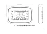
Fig. 2. Lake Extra back case dimensions in inches. ( mm ). 

Summary of Contents for Lake Extra

Page 1: ...Lake Extra Wi Fi Touchscreen Programmable Thermostat ...

Page 2: ...I Contents APPLICATION 1 FEATURES 2 SPECIFICATIONS 3 INSTALLATION 5 WIRING 13 POWER THE THERMOSTAT 30 INSTALLER SETUP 32 OPERATION 43 PROGRAMMING 64 TROUBLESHOOTING 70 ...

Page 3: ...al system compatibility precise comfort control and easy to program Lake Extra provides temperature control for gas oil electric and heat pumps for up to 3 heat 2 cool systems Above all you can remotely monitor and control the heating and cooling system in your home or business you can stay connected to your comfort system wherever you go ...

Page 4: ...e and humidity Menu driven programming make setup effortless Beautiful ergonomic design is smart and sophisticated to match your customer lifestyle Capacitance touchscreen interaction Connect to the Internet to monitor and control your heating cooling system Compressor protection ...

Page 5: ...0 F to 90 F 4 C to 32 C Cooling 50 F to 99 F 10 C to 37 C Operating Ambient Temperature 32 F to 122 F 0 C to 50 C Shipping Temperature 4 F to 150 F 20 C to 65 C Operating Relative Humidity Non condensing IRS 1 5 to 95 ORS 1 5 to 95 Humidity Display Range ...

Page 6: ...nute per month Cool Indication Show Cool On on the screen when Cool is activated Heat Indication Show Heat On on the screen when Heat is activated Auxiliary Heat Indication Show Aux On on the screen when Auxiliary Heat is activated ...

Page 7: ...ct is suitable for your application 3 Installer must be a trained experienced service technician 4 After completing installation use these instructions to check out the product operation Selecting Location Install the thermostat about 5 feet 1 5m above the floor in an area with good air circulation at average temperature See Fig 4 Do not install the thermostat where it can be affected by Drafts or...

Page 8: ...s Unheated or uncooled areas such as an outside wall behind the thermostat Mounting Means Mounts directly on the wall in the living space using mounting screws and anchors provided Dimensions 1 Lake Extra dimensions see Fig 1 2 Lake Extra back case see Fig 2 3 Lake Extra cover plate see Fig 3 ...

Page 9: ...7 Fig 1 Lake Extra dimensions in inches mm ...

Page 10: ...8 Fig 2 Lake Extra back case dimensions in inches mm ...

Page 11: ...9 Fig 3 Lake Extra cover plate dimensions in inches mm ...

Page 12: ...10 Fig 4 Selecting thermostat location ...

Page 13: ...appearance only 2 Use a pencil to mark the mounting holes 3 Remove the wall plate from the wall and if drywall drill two holes in the wall as marked For firmer material such as plaster drill two holes Gently tap anchors provided into the drilled holes until flush with the wall 4 Position the wall plate over the holes pulling wires through the wiring opening See Fig 5 5 Insert the mounting screws i...

Page 14: ...12 Fig 5 Mounting wall plate ...

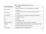
Page 15: ...able 1 and Fig 6 for terminal designation descriptions Insert wires in the terminal block under the loosened screw See Fig 7 2 Securely tighten each screw 3 Push excess wire back into the hole 4 Plug the hole with nonflammable insulation to prevent drafts from affecting the thermostat ...

Page 16: ...ry side of heating system transformer C see Note 2 Common wire from secondary side of cooling system transformer Y Compressor contactor G Fan relay Y2 Second stage cooling O B W see Note 3 Changeover valve for heat pump systems or Heat relay AUX W2 Auxiliary heat relay for heat pump systems or Second stage heat relay E Emergency heat relay for heat pump systems L see note 4 Equipment monitor for h...

Page 17: ...two transformer system remove metal jumper wire between RC and R 2 Common wire is optional when thermostat is used with batteries 3 If thermostat is configured for a heat pump system configure changeover valve for cool or heat 4 L terminal is an input port as system monitor Fig 6 Terminal identifications for system ...

Page 18: ...16 Fig 7 Inserting wires in terminal block IMPORTANT Use 18 gauge thermostat wire ...

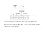
Page 19: ...R SUPPLY PROVIDE DISCONNECT MEANS AND OVERLOAD PROTECTION AS REQUIRED 2 FACTORY INSTALLED JUMPER Fig 8 Typical hookup of conventional single stage heat and cool system with single Transformer 1H 1C conventional ...

Page 20: ...ER SUPPLY PROVIDE DISCONNECT MEANS AND OVERLOAD PROTECTION AS REQUIRED 2 FACTORY INSTALLED JUMPER Fig 9 Typical hookup of conventional single stage heat and cool system with two transformers 1H 1C conventional ...

Page 21: ...19 1 POWER SUPPLY PROVIDE DISCONNECT MEANS AND OVERLOAD PROTECTION AS REQUIRED 2 FACTORY INSTALLED JUMPER Fig 10 Typical hookup of heat only system 1 H conventional ...

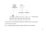
Page 22: ...20 1 POWER SUPPLY PROVIDE DISCONNECT MEANS AND OVERLOAD PROTECTION AS REQUIRED 2 FACTORY INSTALLED JUMPER Fig 11 Typical hookup of heat only system with fan 1H conventional ...

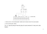
Page 23: ...21 1 POWER SUPPLY PROVIDE DISCONNECT MEANS AND OVERLOAD PROTECTION AS REQUIRED 2 FACTORY INSTALLED JUMPER Fig 12 Typical hookup of heat only power to open and power to close zone valve System ...

Page 24: ...22 1 POWER SUPPLY PROVIDE DISCONNECT MEANS AND OVERLOAD PROTECTION AS REQUIRED 2 FACTORY INSTALLED JUMPER Fig 13 Typical hookup of heat only system with normally open zone valves ...

Page 25: ...23 1 POWER SUPPLY PROVIDE DISCONNECT MEANS AND OVERLOAD PROTECTION AS REQUIRED 2 FACTORY INSTALLED JUMPER Fig 14 Typical hookup of cool only system 1C conventional ...

Page 26: ...CONNECT MEANS AND OVERLOAD PROTECTION AS REQUIRED 2 FACTORY INSTALLED JUMPER Fig 15 Typical hookup of conventional multistage two stage heating and two stage cooling in a single transformer system 2H 2C 2H 1C or 1H 2C conventional ...

Page 27: ...ISCONNECT MEANS AND OVERLOAD PROTECTION AS REQUIRED 2 FACTORY INSTALLED JUMPER Fig 16 Typical hookup of conventional multistage two stage heating and two stage cooling in a two transformer system 2H 2C 2H 1C or1H 2C conventional ...

Page 28: ...CT MEANS AND OVERLOAD PROTECTION AS REQUIRED 2 FACTORY INSTALLED JUMPER 3 O B TERMINAL SET TO CONTROL AS EITHER O OR B IN THE INSTALLER SETUP Fig 17 Typical hookup of single stage heat pump with no auxiliary backup heat 1H 1C heat pump ...

Page 29: ...D 2 FACTORY INSTALLED JUMPER 3 MUST CONNECT THE 24VAC COMMON WHEN USING L THE TERMINAL IS SHOWN AS EQUIPMENT MONITOR 4 O B TERMINAL SET TO CONTROL AS EITHER O OR B IN THE INSTALLER SETUP Fig 18 Typical hookup of multistage heat pump with no auxiliary backup heat 2H 2C heat pump ...

Page 30: ...ED 2 FACTORY INSTALLED JUMPER 3 MUST CONNECT THE 24VAC COMMON WHEN USING L THE TERMINAL IS SHOWN AS EQUIPMENT MONITOR 4 O B TERMINAL SET TO CONTROL AS EITHER O OR B IN THE INSTALLER SETUP Fig 19 Typical hookup of single stage heat pump with auxiliary backup heat 2H 1C heat pump ...

Page 31: ...RED 2 FACTORY INSTALLED JUMPER 3 MUST CONNECT THE 24VAC COMMON WHEN USING L THE TERMINAL IS SHOWN AS EQUIPMENT MONITOR 4 O B TERMINAL SET TO CONTROL AS EITHER O OR B IN THE INSTALLER SETUP Fig 20 Typical hookup of multistage heat pump with auxiliary backup heat 3H 2C heat pump ...

Page 32: ...e in place between RC and R Two Transformer System Connect the common side of the cooling transformer to the C screw terminal of the thermostat wall plate Remove the metal jumper wire between RC and R Mount Thermostat to Wall Plate Align the terminal screw blocks with the pins on the back of the thermostat Push the thermostat straight onto the wall plate until it snaps into place See Fig 21 ...

Page 33: ...31 Fig 21 Mount thermostat to wall plate ...

Page 34: ...enter the Installer Setup 1 See Fig 22 1 Press and release the Key System mode will blink then Press and hold the key for approximately 5 seconds until the screen change Menu number display at bottom right corner See Fig 22 2 Fig 22 1 Fig 22 2 ...

Page 35: ...d press key enter submenu Under submenu Use or to set parameters See Fig 22 3 Fig 22 3 Note See Tables 2 for the Installer Setup Numbers and Settings 3 Press key to exit and confirm the installer setup or press to exit without saving changes ...

Page 36: ...u Number Name Settings Notes 0140 MAC and version See MAC and firmware version 0150 Date and time Set calendar date and time 0160 Schedule Options 0 non programmable 1 7 day programmable The schedule setting will default if changed ...

Page 37: ...s or normally open zone valves 6 cool only conventional 7 2heat 1cool heat pump with auxiliary heat 8 2heat 2cool multistage conventional 9 2heat 1cool multistage conventional 10 1heat 2cool multistage conventional 11 2heat 2cool heat pump no auxiliary heat 12 3heat 2cool heat pump with auxiliary heat Available options and defaults vary by thermostat System selection automatically modifies some de...

Page 38: ...tat controls fan in heating Only shown if conventional system is selected If heat pump is chosen fan defaults to electric 0190 Changeover Valve O B Terminal Energized in Heating or Cooling Heat Pumps Only 0 changeover valve O B terminal is energized in cooling 1 changeover valve O B terminal is energized in heating Only shown if heat pump system is chosen ...

Page 39: ...he range of setting temperature 0 5 difference 0230 Leave mode cooling setting temperature 76 99 leave mode cooling the range of setting temperature 1 difference 24 37 leave mode cooling the range of setting temperature 0 5 difference 0280 Close backlit display 0 show temperature only 1 show main menu 0300 Changeover 0 manual changeover factory setting 1 auto changeover ...

Page 40: ...own only if 0300 is selected 0320 Temperature Indication Scale 0 Fahrenheit factory setting 1 Celsius when it is changed the schedule need to be reprogrammed 0330 1stage hysteresis 1 F 3 F default 2F Fahrenheit value is 2 times of centigrade value 0340 2stage hysteresis 1 F 3 F default 2F Fahrenheit value is 2 times of centigrade value ...

Page 41: ... off 1 10 run time days 2 30 run time days 3 60 run time days 4 90 run time days 5 120 run time days 6 365 run time days Run time based on call for fan 0530 Adaptive Intelligent Recovery 1 Adaptive Intelligent Recovery control is activated system starts early so set point is reached by start of program period 0 Conventional Recovery system starts recovery at programmed time ...

Page 42: ...chedule will default if changed 0580 Minimum Compressor Off Time 5 five minute compressor off time setting factory setting 0 2 3 4 other compressor off time settings 0600 Heat Temperature Range Stop 40 90 temperature range 1 F increments of heating set point Shown in 1 2 C 0610 Cool Temperature Range Stop 50 99 temperature range 1 F increments of cooling set point Shown in 1 2 C ...

Page 43: ... 0 No extended fan operation after call for heat ends 90 Fan operation is extended 90 seconds after call for heat ends Not shown in Cool Only Systems 0660 Extended Fan On Time Cool 0 No extended fan operation after call for cool ends 90 Fan operation is extended 90 seconds after call for cool ends Not shown in Heat Only Systems ...

Page 44: ...er Setup to unlock 0700 Temperature Display Offset 9 F 9 F F as temperature format 4 5 C 4 5 C C as temperature format 0 F 0 C factory setting 0710 Reset thermostat 0 no thermostat reset 1 Resets all Installer Setup Options to default values and resets schedule to default setting Only calendar settings and time are retained ...

Page 45: ...43 OPERATION Fig 23 Thermostat Keys ...

Page 46: ...44 Fig 24 Thermostat Display ...

Page 47: ...number display at bottom right corner 2 Press or key to cutover submenu and press key enter submenu Under submenu Use or to set parameters 3 Press key to exit and confirm the user setup or press to exit without saving changes Note See Tables 3 for the User Setup Numbers and Settings and see chapter INSTALLER SETUP for Operations Reference ...

Page 48: ... Description Settings 0140 See MAC and version 0150 Date and time current calendar date and time 0320 Display temperature in F or C 0 F setting factory setting 1 C setting 0640 Clock format 12 12 hour clock factory setting 24 24 hour clock ...

Page 49: ...ocked keypad 0700 Temperature Display Offset 3 F 3 F F as temperature format 1 5 C 1 5 C C as temperature format 0 F 0 C factory setting 0710 Reset Thermostat 0 No thermostat reset 1 Resets all Installer Setup Options to default values and resets schedule to default setting ...

Page 50: ...and time setting 2 Press to switch date to time follows order year month day hour and minute Press or to adjust the time You can advance the time more quickly by holding the key or key buttons 3 Press to save changes and exit or press to exit without change the date and time Fig 25 ...

Page 51: ...on 2 Press again to select ON or AUTO toggle to re select The selected option blinks 4 Press to save setting Your selection or press to exit without saving changes ON Fan is always on AUTO Fan runs only when the heating or cooling system is on Fig 26 ...

Page 52: ...ess to display options 2 Press again to select an option You may need to press two or three times to make a selection the selected option blinks 3 Press to save setting Your selection or press to exit without saving changes Fig 27 ...

Page 53: ...TO Selects heating or cooling depending on the indoor temperature EMER heat pumps with aux heat Controls auxiliary emergency heat Compressor is locked out Note The AUTO and EMER system settings may not appear depending on how your thermostat was installed Note when under auto mode press key can switch set temperature between heat and cool ...

Page 54: ...re you want the icon until appears above time and the time becomes next scheduled period time 2 Press key to exit and confirm the changes or press to exit without saving changes 3 If you want to exit Override Until please press key Override Until will be also exit until reach the next scheduled period time Note The current day of the week should already be set correctly If not see User Setup to se...

Page 55: ...53 Permanent override Keep user set point permanently 1 Press key once Screen shows Permanent Hold 2 Press or key to adjust temperature you want 3 If you want to exit please press key again ...

Page 56: ...making thermostat changes 1 Press and hold the key for approximately 3 seconds until the screen changes Thermostat locks out all touch keys for 30 seconds to allow for cleaning See Fig 28 2 Use damp cloth slightly moistened with water or house hold glass cleaner to clean the screen Fig 28 When time up press key to return ...

Page 57: ...en and normal operation See Fig 29 Fig 29 IMPORTANT Do not spray any type of liquid directly on the thermostat itself If using household glass cleaner spray cleaner on cloth Then use a cloth to clean the thermostat screen ...

Page 58: ...70 allows you to prevent changes to all of the touchscreen functions In this case all keys are locked and not functional the screen displays a lock icon continuously Even so you can though User setup to unlock keys and restore the touchscreen functions ...

Page 59: ...ove the time when it is time to replace your filter Press after changing the filter to restart the timer To change the reminder interval 1 Press and hold the key for approximately 3 seconds until the screen changes 2 Press or to select the desired interval in days then press to save and exit or press to exit without save Fig 30 ...

Page 60: ...e 1 System setting function 0500 governs the filter interval maximum 2 The days are counted as fan run time so anytime the fan is running the reminder is counting that time against the number of days selected ...

Page 61: ... wireless network Please scan the following code to download Lake Plus APP If you get stuck At any point in this procedure restart the thermostat by removing the thermostat from the wall plate wait a few seconds and snap it back onto the wall plate Return to Step 1 in this procedure which starts on the next page ...

Page 62: ...IFI don t connect the hidden internet download Lake Plus 2 Open APP and register Fig 31 Fig 32 3 After login press top left corner choose WIFI connection and input the WIFI password DON T press the connect and continue next step first Fig 33 Fig 34 ...

Page 63: ...61 4 Press the key on thermostat screen till the flash 5 Now you can press the connect on app app will show processing and after seconds it will show successfully Fig 36 Fig 37 ...

Page 64: ...62 Note 1 IF connect WIFI successfully it will show on the thermostat otherwise will show 2 Each configuration need to be finished within 5minutes otherwise the thermostat will quit to configure ...

Page 65: ...ge Lake will switch to leave mode You can set the temperature you need under leave mode see the following programming to set the temperature If Lake has been under leave mode press on homepage to quit the mode and recover the previous status Fig 38 ...

Page 66: ... Default Program Settings Schedule Period Time Set points Fan Setting Heat Cool Wake 6 00AM 68 F 20 C 78 F 26 C Auto Leave 8 00AM 60 F 16 C 85 F 29 C Auto Return 4 00PM 68 F 20 C 78 F 26 C Auto Sleep 10 00PM 60 F 16 C 82 F 28 C Auto ...

Page 67: ...waken and want your home at a comfortable temperature Leave Period when you are away from home and want an energy saving temperature Return Period when you return home and want your home back to a comfortable temperature Sleep Period when you are asleep and want an energy saving temperature NOTE Schedule times are in 15 minute intervals ...

Page 68: ...change See Fig 39 and 40 Fig 39 2 In this case the time will blink press or to adjust the time Press to turn to next setting 3 Then the temperature will start to blink press or to adjust the temperature Press to turn to next time period Fig 40 ...

Page 69: ...me periods Then Press to turn to next day until completing the setting of a week 5 End of Program Setting You may press key to exit and confirm the program setting or press to exit without saving changes NOTE The Fan setting is auto as default and cannot be programmed ...

Page 70: ...lows 1 Select the program for Monday complete the setting of Monday and press the icon appears on the screen and the icon Will blink that indicates Waiting to be selected or skipped Press to select press to skip 2 Copy to Thursday press or to select Thursday then press to finish the copying and the icon disappears 3 Copying for other days please repeat from the Step 1 to 2 One time you can copy to...

Page 71: ...rmostat can reset schedule setup option to default setting Press and hold key for approximately 3 seconds until the screen change as Fig 41 then release key Now the setting of schedule reset to default setting as table 4 Fig 41 ...

Page 72: ... Check 24VAC between C and R Temperature settings do not change The upper or lower temperature limits were reached Check temperature set points Check Installer Setup Numbers 0600 or 0610 modify as needed The keypad is fully locked Check Installer Setup Number 0670 to change keypad locked options ...

Page 73: ...t minimum off time is activated Wait up to five minutes for the system to respond System selection is not set to Heat or Cool Set system Selection to correct position System type Selection is incorrect Check Installer Setup Number 0170 and make sure correct System type is chosen ...

Page 74: ...uipment is not operating Check wiring Check Installer Setup Number 0170 and make sure correct system type is chosen Verify operation of equipment in System Test mode Fan does not turn on in a call for heat electric furnace Fan Control in Heating is set to Gas or Oil Furnace Setting 0180 Set Fan Control in Heating to Electric Furnace Setting 0180 ...

Page 75: ...staller Setup Number 0190 to match the changeover required by the installed heat pump Both the heating and cooling equipment are running at the same time The heating equipment is not a heat pump but the System Type is set to Heat Pump Set System Type Installer Setup Number 0170 to match the installed heating and or cooling equipment Heating and cooling wires are shorted together Separate the short...

Page 76: ...tem Type Installer Setup Number 0170 to match the installed heating and or cooling equipment Heating equipment does not turn off and heat temperature setting is set below room temperature Heating equipment is not a heat pump but System Type Installer Setup Number 0170 is set to Heat Pump Set System Type Installer Setup Number 0170 to match the installed heating and or cooling equipment ...

Page 77: ...stalled equipment Heat On is not in the display System is not set to Heat and or temperature is not above room temperature Set the system setting to Heat and set the temperature setting above the room temperature Cool On is not in the display System is not set to Cool and or temperature is not below room temperature Set the system setting to Cool and set the temperature setting below the room temp...

Page 78: ...sor minimum off timer is active Wait up to five minutes for the cooling or heating heat pump equipment to turn on Screen Locked appears on the screen and the keys do not respond The keypad is locked Check Installer Setup Number 0670 to change keypad locked options ...

Reviews: