Assembly
Information brochure · H-50.2 system components
V02R00 · 1134319 · 2022-11
25
5.7
Information on attachment of the access ladder to the structure
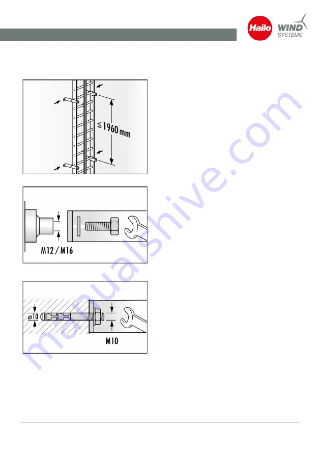
Fig. 15: Distance between anchorage points
Fig. 16: Access ladder assembly on threaded
bush M12/M16
Fig. 17: Anchor plug attachment in concrete (min.
C20/25)
The anchorage points and their connections
(brackets, means of attachment) must be able
to absorb the loads.
When dimensioning the ladder bracket and
the anchorage points, it must be ensured that
a dynamic load of 6 kN and a static load of
15 kN can be absorbed by the overall system.
The anchorage points must not exceed a max-
imum vertical interval of 2,000 mm.
Advisable is 1,960 mm for a rung spacing of
280 mm fig. Distance between anchorage
points, Page 25. Larger intervals must be
agreed beforehand with Hailo Wind Systems.
The anchorage points must be positioned in
pairs at the right and left of the ladder respec-
tively at the same level.
The substrate for the structure for the anchor-
age points must be sufficiently dimensioned,
and be suited for the aforementioned loads.
Suitable substrates are:
Steel structures with threaded bushes (min. M
12) fig. Access ladder assembly on threaded
bush M12/M16, Page 25or screw connec-
tions using though holes, anchor plug attach-
ment to concrete structures with a minimum
concrete quality of C 20/25, whereby only
plugs approved under building regulations
may be used fig. Anchor plug attachment in
concrete (min. C20/25), Page 25.
Masonry is not suitable as a substrate for an-
chor plug attachment. In these cases, an an-
chorage using a through hole with counter-
plate in the masonry is conceivable. However,
it is essential that an engineering agency plan
this and provide the corresponding verifica-
tion.


