Assembly
Information brochure · H-50.2 system components
V02R00 · 1134319 · 2022-11
31
5.12
Installation of the rail connector
Installation at rail joint
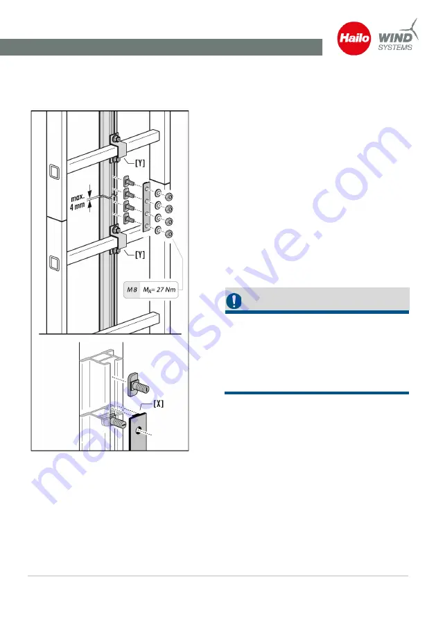
Fig. 25: Rail connector assembly
Assembly of two fall protection rails using a rail
connector.
The hammerhead screw must be rotated in the
profile of the fall protection rail and positioned
with the square neck in the opening of the rail
profile. The lug protruding from the rail con-
nector [X] must also be positioned in the open-
ing of the rail profile.
This is the only way to ensure a secure connec-
tion, see chapter Assembly using hammerhead
screw, Page 27.
Interval between the fail protection rails (rail
joint) = 0 mm to max. 4 mm.
A maximum air gap of 4 mm can be left at the
rail joint to allow for length compensation due
to temperature fluctuations.
IMPORTANT!
At each rail joint, the fall protection rails must
be joined together with a rail connector.
At each rail joint, the fall protection rails must
be attached to the ladder rungs using a rung
clamp [Y] at the end of the bottom and begin-
ning of the top fall protection rail.


