Assembly
Information brochure · H-50.2 system components
V02R00 · 1134319 · 2022-11
36
5.16
Assembly and use of the plug-in access aid
Information about the plug-in access aid:
The H-50.2 access aid is only intended for
use in the H-50.2 fall-arrest system, and
may only be used in combination with a H-
50.2 fall protection rail.
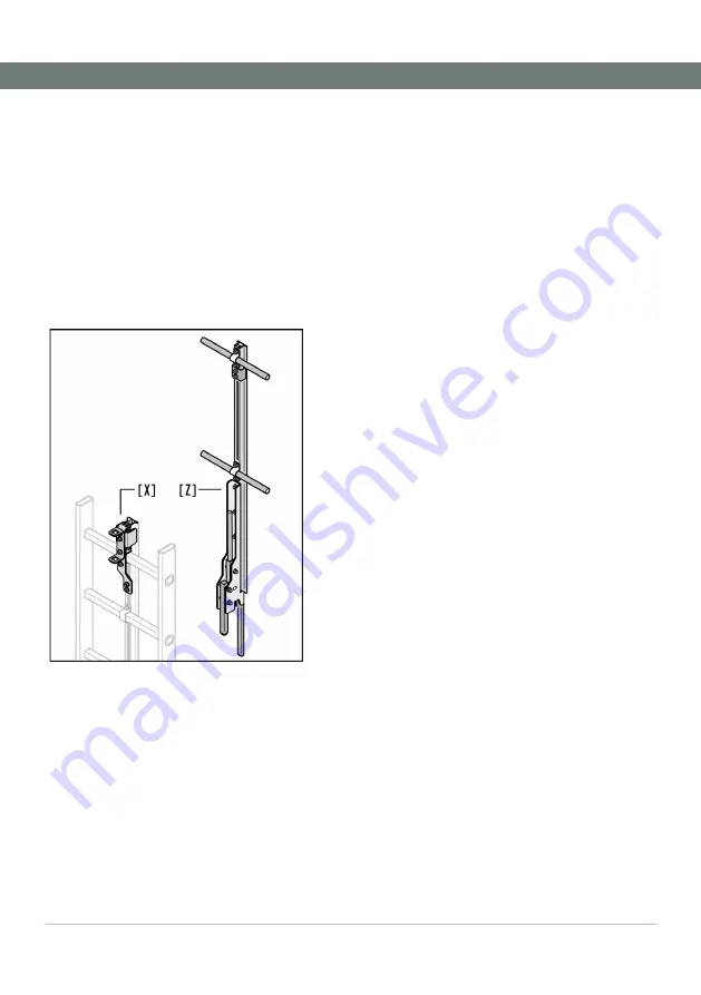
If only one H-50.2 plug-in access aid [Z]
will be used for several H-50.2 fall-arrest
systems, the coupling unit [X] must also be
installed on each vertical ladder to do so.
Fig. 32: Installation of the plug-in access aid
Installation of the coupling unit [Y] on the
fall protection rail:
The fall protection rail must protrude
125 mm above the top ladder rung.
1.
►
Insert the connector [X-1] into the fall
protection rail [Y] and use 4 grub
screws to secure it.
2.
►
Use a rung clamp on the top ladder
rung to attach the fall protection rail
when doing so.
3.
►
Then screw the distance bolts [X-8] by
hand.
4.
►
Insert the end stop [X-2], the pressure
springs [X-3] and the reinforcement [X-
4].
5.
►
Place the cover [X-5] on it and addi-
tionally secure the cover with 2 ham-
merhead screws
[X-6].
6.
►
Attention!
The top edges of the cover [X-5] and
the fall protection rail [Y] must be flush
7.
►
Screw the entire coupling unit together
with the cover [X-5] and the bracket [X-
7] to the fall protection rail or the lad-
der rung.
Insertion of the plug-in access aid:
1.
►
Insert the access aid into the bracket
[X-7] and into the profile of the fall
protection rail [Y] as shown.
2.
►
Pull the lever [Z-1] so that both snap
hooks [Z-2] can be guided into the
opening in the cover [X-5].
⇨
The lever [Z-1] locks in place auto-
matically when released, and se-
cures the access aid.
3.
►
Check that the access aid fits tightly
before use.
Removal of the plug-in access aid:
1.
►
Operate the lever [Z-1] to unlock the
two snap hooks [Z-2] and to pull the
access aid upwards to remove it.


