20
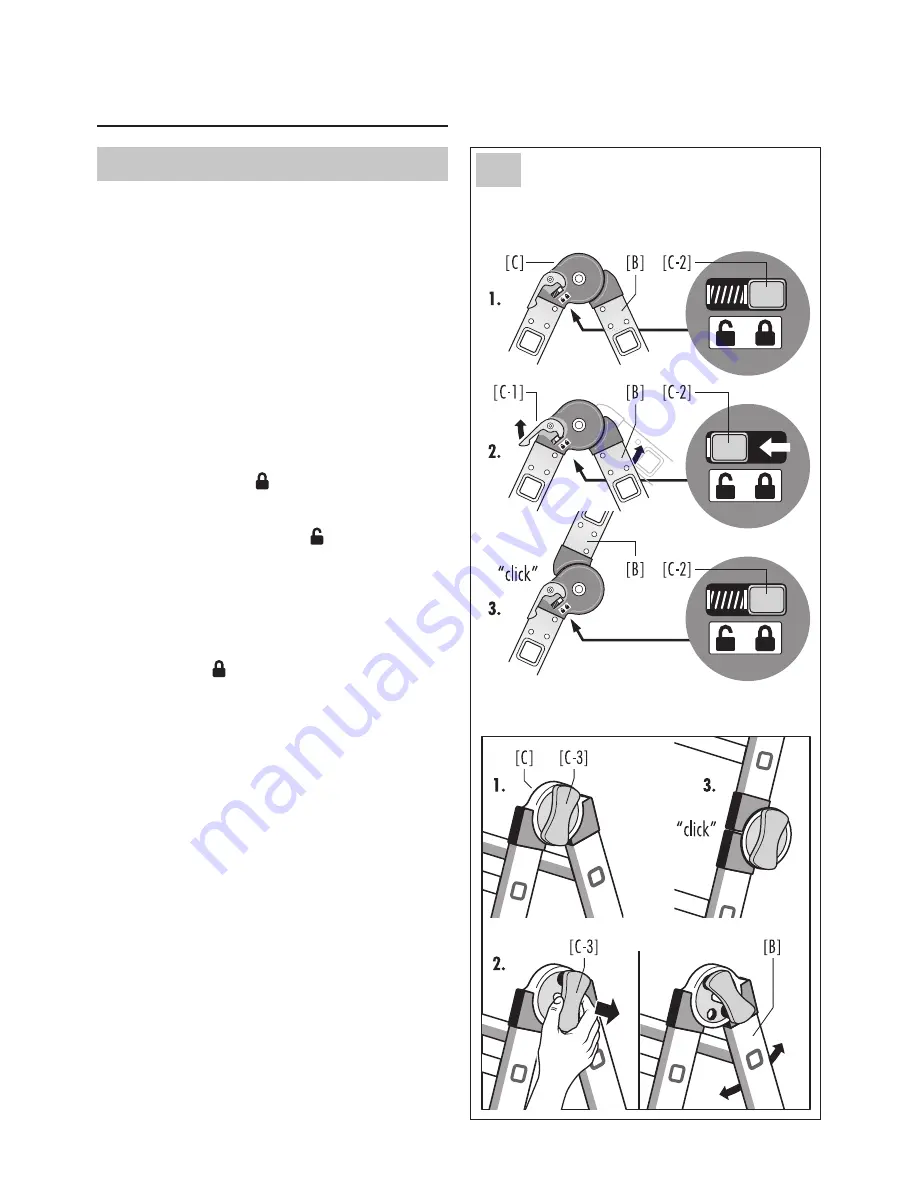
Using the hinge joint [C], the ladder is converted into
either a stepladder or single ladder.
The foldable ladder part [B] is first unlocked and – af-
ter the ladder has been brought into the desired set-up
position – locked again.
For adjusting one of the ladder parts, both of the
safety joints on opposite sides of the ladder have to be
activated.
Item no. 7512-xxx, 7516-xxx, 7520-xxx
1. Original position: the ladder is locked, and the stop
button [C-2] is in the position.
2. Pull up the lever [C-1], and the ladder is unlocked.
The stop button [C-2] is in the position.
The ladder part [B] can now be adjusted to the
desired position.
3. The ladder part [B] audibly clicks into place auto-
matically. The ladder is locked, and the stop button
[C-2] is in the position.
This procedure is repeated once again to bring it into
another set-up position.
Item no. 7524-xxx
1. Original position: the ladder is locked, and the clamp
[C-3] is pushed in.
2. Pull out the clamp [C-3] and place it on the safety
joint by turning it slightly.
The locking opening is free, the ladder is unlocked
and the ladder part [B] can now be adjusted into the
desired position.
3. The ladder part [B] audibly clicks into place auto-
matically. The ladder is locked, and the clamp [C-3] is
pushed in.
5.2 Adjusting for the step or single ladder
Item no. 7512-xxx
Item no. 7516-xxx
Item no. 7520-xxx
Item no. 7524-xxx
5. Assembly / operation
5.2
Summary of Contents for M80
Page 128: ...128 7512 xxx 4 x 3 7516 xxx 4 x 4 7520 xxx 4 x 5 7524 xxx 4 x 6...
Page 129: ...129 2 1 ja 1 2 3 4 5 6 7 8 9 10 11 12 129 129 130 131 131 135 138 139 139 139 139 140 EN 131 4...
Page 133: ...133 ja 5 3 A D D A 1 D 2 D A 3 D 5 3...
Page 134: ...134 5 5 4 A F C D B C D C C D 5 4...
Page 135: ...135 ja 6...
Page 136: ...136 6...
Page 137: ...137 ja 3 2 1m...
Page 138: ...138 7...
Page 140: ...140 1 2 3 4 5 6 12...
Page 141: ...141 ja 1 6...
Page 142: ...142...
Page 143: ...143...


