24
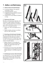
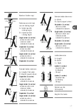
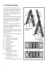
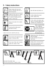
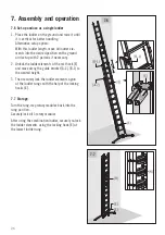
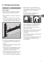
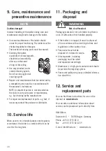
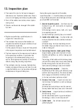
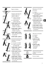
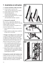
7.1 Set-up options (schematic diagram):
A = Free-standing stepladder with additional
extension ladder (3-section)
B = Free-standing stepladder (2-section)
C = Single ladder with extended extension section
and extension ladder (3-section)
D = Single ladder with extended extension section
(2-section)
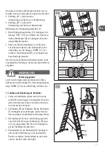
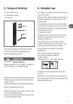
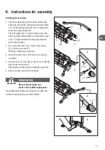
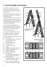
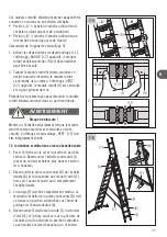
7.2 Function of the LOT system
With the aid of the LOT system, the ladder can be
positioned and set up vertically if the ground has
different height levels. Floor unevenness can be
compensated up to a height of 15 cm.
1. Open the foot pedal [A-1] and adjust the
crossbar [C].
2. Close foot pedal and check ladder for secure
footing before using.
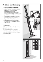
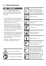
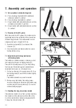
7.3 Adjustment and locking mechanism
with locking hooks
The ladder or a ladder element is locked on a lad-
der rung using the pair of locking hooks [E].
The anti-lift security device [E-1] on the locking
hock secures the ladder against unintentional
movement and serves as a transport lock.
1. Pull up on the anti-lift security device [E-1] on
the locking hook [E] and lift the ladder slightly
to unlock it.
The ladder elements can now be moved.
2. Before using the ladder, the locking hooks
must be correctly positioned on the ladder rung
and the anti-lift security device [E-1] must be
automatically engaged.
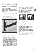
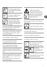
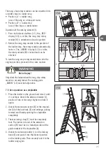
7.4 Handling the rung-step rotary module
The extension ladder [J] on the 3-section combina-
tion ladder and the extension section [B] on the
2-section combination ladder are equipped with
3 rung-step rotary modules [H].
7. Assembly and operation
7.1
7.2
7.3

