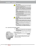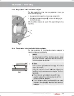
mandoteX – Assembly
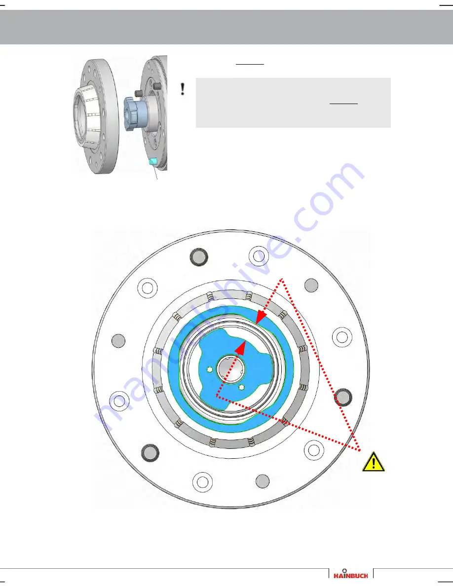
Fig. 14
3. Screw in the shorter cylindrical screws [E] and tigh-
ten them with the required tightening torque.
NOTE!
Mark / label the now assembled shorter screws
[E1] for the later alignment in the assembled
condition.
The flange of the clamping device adapter is assemb-
led to the clamping device.
Step 3
For adjusting the angle the following steps are to be
done:
Fig. 15
Order h49 7144.907-333
35
E1


