Sensor & Intelligent Control
Attention
1. Please read the instructions carefully before using this product and keep it well for all
users to read at any time.
2. The sensor should be installed by qualified electrician and ensure power is off before the
installation.
3. We reserve the right to modify any incorrect text, image and necessary technical param-
eters.
4. Any unauthorized modification is forbidden, otherwise all guarantees will be immediately
invalid.
Installation precautions
1. Microwave sensor can be installed in any lamp except the one with
full metal shell.
2. The detected surface cannot be shielded by metal objects.
3. Make sure the microwave module is completely exposed outside.
4. The detection surface of the sensor module shall be installed
facing the detection area.
5. Should be kept away from the driver to avoid interference genera-
tion and lamp flashing.
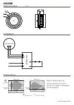
6. Wiring must be strictly in accordance with the wiring diagram to
avoid short circuit.
Application Environment
1. Suitable for indoor installation to avoid false triggering due to exter-
nal factors such as rain, wind or tree swing.
2. Shall not be installed in the place with all four metal shelters and
small space (such as galvanized-iron roof ).
3. Shall note be mounted installation, so as to avoid false trigger
caused by the lamp itself shaking.
4. Shall not be installed next to large operating machines such as venti-
lator/ceiling fan to avoid false triggering caused by machine vibration.
User Notes
1.Microwave can penetrate walls or glass thinner than
<
20mm and
attenuate if thicker than
<
20mm.
2. The driver voltage shall be stable and float within 10%.
3. Detection area will be affected by speed of motion, mounting height
and movement volume.
4. Conduct test on sunny days without the lampshade which will affect
the tested lux value.

