background image

www.haiwell.com

Haiwell PLC - Temperature & Humidity Module User Manual

4 / 23

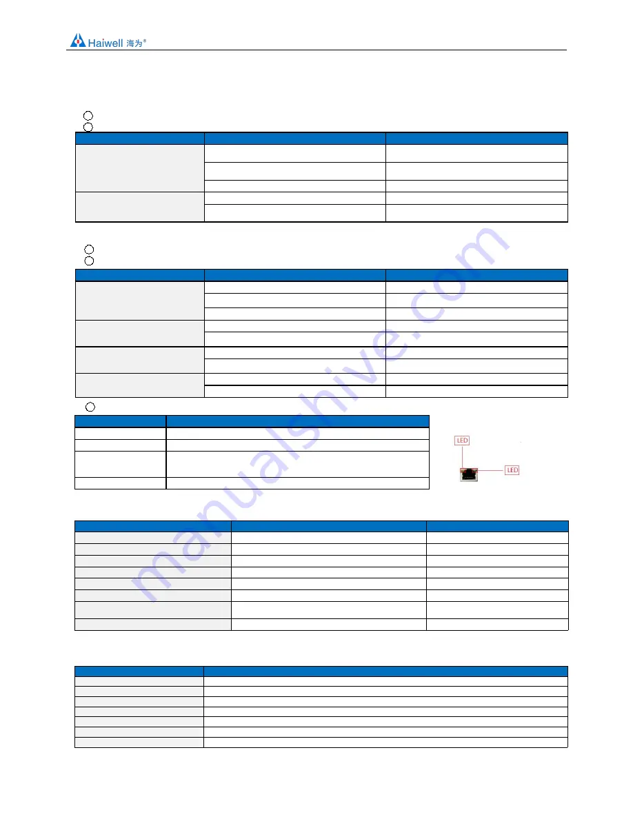
2. Indicator description

2.1 Indicator description of H04DT, H32DT

1

PWR

Power indicator, green. Normally on-power normal; off - power abnormal.

2

LINK: Multi-status indicator .three colors(Red. Yellow. Green) ,as follow:

Reference processing mode

Module bus state

LINK indicator state

Normal

MPU didn’t identify the module and no

communication

No light

MPU has identified the module but no

communication

Constant light in green

Serial(H32DT) or parallel port in communication

Green jitter: indicator on 30ms and off 30ms

Firmware upgrade failed, reupgrade

the module firmware

Without serial or parallel port in communication

Red flicker: indicator on 0.5s and off 0.5s

With serial or parallel port in communication

Red is darkened and jitter alternately: indicator off

0.5s and jitter 0.5s

2.2 Indicator description of H04TC, H04RC, H08TC, H08RC

1

PWR

Power indicator, green. Normally on-power normal; off - power abnormal.

2

LINK: Multi-status indicator .three colors(Red. Yellow. Green) ,as follow:

Reference processing mode

Module bus state

LINK indicator state

Normal

No communication of module

No light

MPU has identified the module but no

communication

Constant light in green

Serial or parallel port in communication

Green jitter: indicator on 30ms and off 30ms

Parallel power supply not enough,

must connect to external power

supply

Without serial or parallel port in communication

Yellow flicker: indicator on 0.5s and off 0.5s

With serial or parallel port in communication

Yellow is darkened and jitter alternately: indicator off

0.5s and jitter 0.5s

Firmware upgrade failed, reupgrade

the module firmware

Without serial or parallel port in communication

Red flicker: indicator on 0.5s and off 0.5s

With serial or parallel port in communication

Red is darkened and jitter alternately: indicator off

0.5s and jitter 0.5s

Hardware failure and maintenance

Without serial or parallel port in communication

Constant light in red

With serial or parallel port in communication

Red jitter quickly: indicator on 30ms and off 30ms

3

RJ45 Ethernet indicator: there are two Ethernet LEDs, green and yellow, as shown on the right picture:

Color

Status description

Green light is always on

Physical connection of TCP module and external device is normal;

Green light goes out

TCP module fails to connect with external device or the module itself is abnormal

Yellow light blinks

TCP module is connected to an external device normally, and blinking frequency indicates

the data transmission speed. When speed is fast, human eye is not easy to distinguish it,

at this time, yellow light is long brignt.

Yellow light goes out

No data transmission communication of TCP module and external device

3. Power supply specification

Item

DC Power Supply

AC Power Supply

Power supply voltage

24VDC

-15%~+20%

100~240VAC

Power supply frequency

——

50~60Hz

Instantaneous surge

MAX 20A 1.5ms @24VDC

20A 1.5ms MAX @220VAC

Power loss time

10ms or less

20ms or less @220VAC

Fuse

0.3A

250V

2A, 250V

24V Output voltage (for input and expansion)

None

24V, -15%~+15%, 200mA (Max)

Isolation Type

No Electrical isolation

Transformer isolation or optoelectronic

isolation,1500VAC/1 minute

Power Protection

DC input power polarity reverse, over voltage protection

DC 24V output over current protection

4. Environmental specifications for product

Item

Environment Specification

Temperature/humidity

Operating temperature:0~+55

Storage temperature:-25~+70

Humidity: 5~95%RH, No condensation

Vibration resistance

10~57 HZ, amplitude=0.075mm, 57HZ~150HZ acceleration=1G, 10 times each for X-axis, Y-axis and Z-axis

Impact resistance

15G, duration=11ms, 6 times each for X-axis, Y-axis and Z-axis

Interference immunity

DC EFT:±2500V

Surge:±1000V

Over voltage resistance

500VAC/1min between DC terminal and PE terminal

Insulation impedance

B

etween AC terminal and PE terminal

@500VDC,>=5

,

all input/output points to PE terminal @500VDC

Operating environment

Avoid dust, moisture, corrosion, electric shock and external shocks

Summary of Contents for H04DT

Page 1: ...m Haiwell PLC Temperature Humidity Module User Manual Xiamen Haiwell Technology Co Ltd www haiwell com Haiwell PLC User Manual Programmable Logic Controller Temperature Humidity Module User Manual App...

Page 2: ...se 1 Expand module through the host PLC parallel port 10 1 1 Module power supply 10 1 2 Temperature modules need t be written any conversion program read the current temperature value directly when ac...

Page 3: ...35 0 5 6 7 8 9 10 11 12 0 1 2 3 4 5 6 7 AI AI LINK POW RT1 RT0M RT2M RT0 RT2 RT0 RT2 RT3M GND RT3 A RT1M B RT1 RT3 RS485 RT4M RT6M RT4 RT6 RT4 RT5M RT7 RT7 RT7M RT5 RT5 RT6 1 2 3 4 ON DIP H08RC 13 14...

Page 4: ...d maintenance Without serial or parallel port in communication Constant light in red With serial or parallel port in communication Red jitter quickly indicator on 30ms and off 30ms 3 RJ45 Ethernet ind...

Page 5: ...0 50 mV 0 100 mV Resolution 0 1 0 1 Input impedance 6M 6M Maximum input range 13V 30mA Input indication LED light ON means normal OFF means external disconnection Response time 560ms 4 Channel 880ms 8...

Page 6: ...code H32DTfunction description 00H Low byte for module code and high byte for module version number 01H Communication address 02H Communication protocol The low 4 bit of the low byte 0 N 8 2 For RTU...

Page 7: ...1 input value 11H channel 2 input value channel 2 input value 12H channel 3 input value channel 3 input value 13H channel 4 input value channel 4 input value 14H channel 1 signal type note 2 channel...

Page 8: ...note 5 21H channel 1 engineering lower limiting value channel 1 engineering lower limiting value 22H channel 2 engineering lower limiting value channel 2 engineering lower limiting value 23H channel...

Page 9: ...bit indicates 1 channel 0 normal 1 disconnection 5 5 Use the engineering value mark Each bit indicates 1 channel 0 No 1 Yes 9 Expansion modules installation The PLC should be secured to an enclosed c...

Page 10: ...dule is added external power supply it can still work this time the module will automatically determine and give priority to external power supply 1 2 Temperature modules need t be written any convers...

Page 11: ...uration that is the actual temperature value for example you can set 1 on decimal places of Haiwell Cloud SCADA settings So that when the PLC read AI0 value AI0 123 that is the actual value of 12 3 th...

Page 12: ...uted installation is very important for the system which needs to collect and monitor a large number of decentralized digital or analog signals temperature humidity differential pressure blowing rate...

Page 13: ...configured via programming software tools remote modules recommended 2 It can be configured via the hardware configuration and TO instructions when the module is hung behind the host PLC through the p...

Page 14: ...ameter configuration Click to exit enter the configuration interface as shown below We can change the module name address IP subnet mask baud rate data format and other communication parameters in the...

Page 15: ...ut values are stored in 10H 13H of H04RC module 3 PLC program Host PLC wants to read the 4 channel temperature values of remote IO module H04RC 4 channel temperature sensors for PT100 2000 8500 indica...

Page 16: ...ed in the V10 V17 as follows 1 8 Remote IO appliciation example Haiwell Cloud configuration communicates directly with H08TC module 1 1 Open Haiwell SCADA software select the new project choose to add...

Page 17: ...can see that when choosing to measure the temperature and humidity the analog input register does not appear two consecutive addresses such as the above channel 2 and 3 are connected to temperature h...

Page 18: ...ensor 4 how to replace broken module First let s look at the hardware wiring How to connect H32DT with the remote module tools of PLC software Hardware connection and power supply PC side USB transfer...

Page 19: ...rent temperature is 25 1 2 No 1 sensor serial number 3904 16A0 A719 FF28 that is 1 sensor serial number 3 Numerical 1250 indicates that the maximum value of engineering quantity displayed by the chann...

Page 20: ...sors we have to save the configuration parameters of H32DT module this step is very important The back will introduce the application occasions The specific operation is as follows in the menu bar of...

Page 21: ...default station number defaults to 1 and supports Modbus protocol So communication program is as follows The above introduce the normal use steps and methods for H32DT Then we will introduce how to d...

Page 22: ...through the remote module tool import the previous configuration table and finally click parameters download to download the parameters into the module The each position s temperature value and the se...

Page 23: ...ng to the 16 sensors in channel 2 so the communication program is as follows What is the role of configuring the number of sensors A If the number of sensors in the H32DT channel is less than the numb...

Reviews: