- 3 -
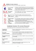
Use correct power
source.
Operate your system within the specified power voltage. An incorrect
power supply may cause
Maintenance Cautions<For Maintenance Personnel>
Use the following safety precaution internal inspection.
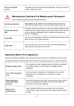
Discharge capacitors.
High voltage may be retained in the capacitors if the high-tension
circuit several minutes after you have turned the power switch off.
Check that power is
OFF
To prevent an electrical injury due to erroneous power switching, make
sure that the main power supply and the system power switch are both
in the off position. Additionally, attach a safety label showing that
service is in progress.
Avoid EMI.
Take care not to damage the ESDs (Electrostatic Sensitive Devices) by
static electricity from carpet and cloths.
Avoid dust.
Wear a safety mask so as not to breath in dust during inspection or
cleaning inside your system instruments.
Operation Notes <For operators>
Observe the following operation notes, otherwise the system failure or deterioration can result. And
periodical inspection and maintenance are required for keeping the system in an optimum condition.
Backup important data.
The waypoint and other registered data may become unreadable
by unexpected failure. We recommend recording this data
separately.
Use correct transducer
only.
If you use incorrect transducer, the transmitter circuit may be
damaged due to a matching error. Consult is for system
information.
Check transducer
Connection before
power on
Do not turn the power switch ON if the transducer is disconnected
or if it is not inserted into the water. If done, the transducer or
transmitter circuit may be damaged.
Always clean
the transducer
Since transducer performance can drop due to accumulated
bottom growth, keep the transducer clean. Never paint transducer
surface.
Summary of Contents for Smart10 Series
Page 8: ... 8 ...
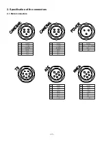
Page 11: ... 11 2 Specification of the connectors 2 1 Metal connectors ...
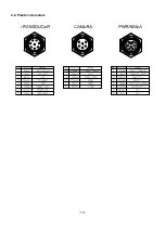
Page 12: ... 12 2 2 Plastic connectors ...
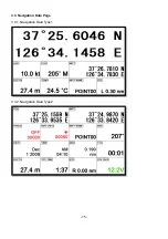
Page 15: ... 15 3 3 Navigation Data Page 3 3 1 Navigation Data Type1 3 3 2 Navigation Data Type2 ...
Page 19: ... 19 ...
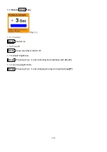
Page 25: ... 25 Fig 1 3 3 When finishing press to exit ...
Page 28: ... 28 Fig 1 6 3 ...
Page 39: ... 39 2 2 Detail Choose the AIS target and press ENTER 2 3 Goto Choose the AIS target and press ...
Page 45: ... 45 ...
Page 51: ... 51 2 9 Sorting MENU Userdata WPT List MENU Sorting the order of WPT on the list ...
Page 63: ... 63 The maximum range of Correction Offset is 5nm ...
Page 71: ... 71 ...
Page 79: ... 79 ...
Page 95: ... 95 ...
Page 98: ... 98 Smart10 Flush Mounting Smart7 8 Flush Mounting ...
Page 111: ... 111 ...

