background image

-12-


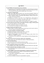
2. Checking and adjustment of Drill Carriage Assy.   

(In case of combination with □49 Drill Carriage Assy.) 

  Set Drill Head onto Pole Base. While moving 

feeding handle, tighten 4 pieces of hex. socket set 

screws on Drill Carriage Assy. in good balance with 

hex. bar wrench and adjust the gap between Pole 

and Drill Carriage Assy. 


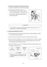
3. Checking and adjustment of clutch 

  As Friction Plates wear out, the clutch becomes easy to slip. When this happens, readjust 

the clutch using clutch adjusting tools. 

1) Remove Hex. Socket Cap Plug 1/8” from Gear Case by Hex. Bar Wrench (5mm). 

2) Insert the tip of Clutch Adjusting Pin into the hole, where the plug 1/8” is removed, in parallel 

with the main shaft. While doing this, slowly turn the Main Shaft by hand and further insert 

Clutch Adjusting Pin till the Main Shaft is locked. 

3) Hold Clutch Adjusting Pin by your hand, hang the Spanner 36mm on the Main Shaft. Using 

Torque Wrench, fasten the clutch. 


CAUTION


If hex. socket set screws are fastened too tight, feeding handle gets heavy. When 
slide plate is worn and starts to rattle, replace it. 


CAUTION


Tightening  more  than  specified  value  might 
cause the damage to clutch adjusting pin and 
Drill Motor. 

Model


Tightening 

Torque


Tightening 

Direction


SPN-202Uw 

87N

Left 


Hex. Bar Wrench 

Clutch Adjusting Pin 

Torque Wrench 

Right


Spanner 36mm 

Left


Summary of Contents for SPN-202Uw

Page 1: ...CTIONMANUAL Thank you for purchasing our products Before using please read Instruction manual carefully and use the machine safely by following the instructions After reading please keep it where anyo...

Page 2: ...if the user uses the machine wrongly it would be the risks that the user could be died or injured CAUTION It is assumed that if the user uses the machine wrongly it would be the risks that the user co...

Page 3: ...ION 6 3 SPECIFICATIONS 7 4 STANDARD ACCESSORIES 7 5 APPLICATIONS 7 6 GENERAL DRAWING AND SPECIFICATIONS IN OPERATION 8 7 OPERATIONAL INSTRUCTIONS 1 Anchoring Core Dill 9 2 Anchoring Core Drill by Anch...

Page 4: ...rts Wear rubber gloves and slip stopper footwear Wear cap or hair cover in case that you have long hair 5 Wear safety glasses Wear safety glasses during working If there is dust please wear the dust m...

Page 5: ...ke sure that the key and the wrench which are used for the inspection and adjusting are removed 14 The electric machines are maintained carefully Regarding exchanging the options please follow the ins...

Page 6: ...er voltage which is indicated on the nameplate In case that you apply for the voltage which is over the indicated voltage it will cause the accidents 7 Fix the Pole Base properly It is extremely impor...

Page 7: ...ore Bit facing to the drilling surface It causes the damages for core bit and core drill 4 When starting the drilling please wait until the rotating is increased Regarding the drilling work turn the s...

Page 8: ...utside of Main Shaft Clamp Adjust Bolt Hex Socket Set Screw Plug Motor Water Cock Switch Built in Circuit Breaker Grip Clamp Adjust Bolt Hex Socket Set Screw 247 328 Cord 5m Lock Dial Feeding Handle G...

Page 9: ...UNC Inside G 1 2 Drill Head Weight Excluding cord 11 0kg 4 STANDARD ACCESSORIES Hex Bar Wrench 4mm 1 Instruction Manual 1 5 APPLICATIONS This tool is Core Drill for drilling in concrete Core drilling...

Page 10: ...ING AND SPECIFICATIONS IN OPERATION Core drill installed on to 49 Pole Base SB 491 1000 49 Pole Base Water Collector Water Collector Fitting Drill Head Feeding Handle Bolt Square Washer Hex Nut Core B...

Page 11: ...st leveling with leveling bolts so as to eliminate rattling of pole base After completion of adjustment secure leveling bolt with wing nut 6 Tighten hex nut W1 2 to secure Pole Base 7 Set desired rota...

Page 12: ...oosen hex nut and dismount Pole Base WARNING When drilling a through hole take proper measures to provide for protection on the other side where core bit penetrates WARNING To prevent accidental start...

Page 13: ...water 2 Maintenance for motor After entire operation is over secure Drill Head onto Pole Base run motor with no load and remove dirt and dust from motor interior 2 Regular Servicing 1 Checking of Car...

Page 14: ...5mm 2 Insert the tip of Clutch Adjusting Pin into the hole where the plug 1 8 is removed in parallel with the main shaft While doing this slowly turn the Main Shaft by hand and further insert Clutch A...

Page 15: ...ning periodically If found loose tighten it 9 FOR REPAIRING For repairing your machine contact CONSEC s authorized representative 10 WARRANTY We will guarantee the HAKKEN Core Drill SPN 202Uw for 6 mo...

Page 16: ...14...

Page 17: ...15...

Page 18: ...16...

Page 19: ...17...

Page 20: ...18 Main office 4 6 8 Shoko Center Nishi ku Hiroshima 733 0833 Japan International Department 1 7 5 1 Sakaimachi Naka ku Hiroshima 730 0853 Japan Phone 81 82 297 3231 Fax 81 82 297 3230 E2280 1...

Reviews: