27 / 47
Hakki Pilke 50 Pro
Translation
Version 1-2018
4.
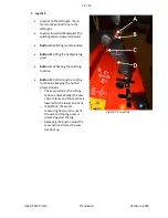
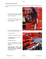
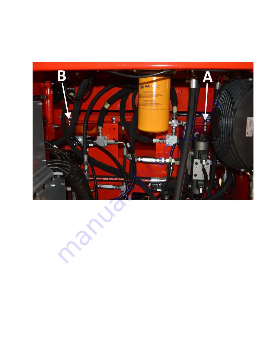
Sensor B (Figure 22) is used to determine the point at which the splitting cylinder changes
direction during the splitting cycle, i.e. how close to the splitting beam the splitting blade goes. If
necessary, change the position of the sensor, as instructed in section 3 above.
Note! The covers and guards must be reattached after maintenance.
Figure 22.
4.5.
Using the out-feed conveyor
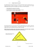
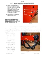
The out-feed conveyor can be controlled horizontally and vertically. The safety zone for the out-feed
conveyor is 10 metres. When operating the machine, the maximum permitted angle of the out-feed
conveyor is 40°. The running speed of the out-feed conveyor can be freely adjusted with adjustment
screw C (Figure 10). If the conveyor is jammed for any reason, the out-feed conveyor must be stopped
with lever B (Figure 10) and the machine shut down before the cause is removed. If the cause for the
failure is in the debris removal mechanism, you can reverse the conveyor belt for a short distance with
lever B (Figure 10). There must be at least 50 cm between the end of the out-feed conveyor and the pile
of processed firewood.
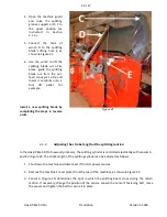
The tightness of the out-feed conveyor belt (and the belt’s alignment) can be adjusted as follows:
1.
Loosen fastening nut A (Figure 23).
2.
Tighten/loosen the belt with nut B in Figure 23 (the same amount on both sides of the belt). If the
belt is crooked, loosen nut B (in relation to the spring) on the side towards which you wish to align
the belt better.
3.
When the conveyor belt is at the correct tension and properly aligned, tighten the fastening nuts
(A) on both sides.


