background image

HAKKI PILKE RAVEN 

TRANSLATION 

VERSION 1-2015 


6.


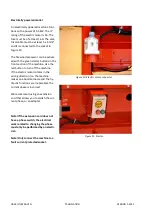
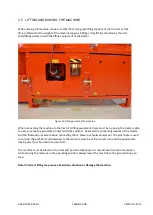
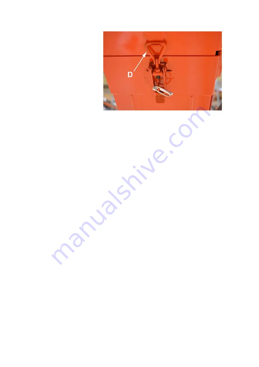
Use a winch to lift the conveyor to the 
desired angle (max 40°) and lock the 
upper section of the output conveyor to 
the operating position using lock D (Fig-
ure 8). 


Figure 8. 

Place the output conveyor in the transport position as follows:  


1.


Turn off the machine. 

2.


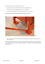
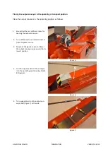
Release lock D (Figure 7) and lower the conveyor to the lowest possible position with the winch. 

3.


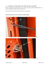
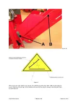
Turn support bar C (Figure 7) to a position over the belt, and turn the upper section of the con-
veyor onto the lower section using handle B (Figure 5). 

4.


Turn the conveyor to the middle position (only in machines with a pivoting conveyor). See Sec-
tion 3.6.  

5.


Lift the conveyor with the winch until it locks into the raised position. Ensure that lock A (Figure 
5) settles properly into place. 


Note!  Do not stand on the output conveyor! Do not use the winch if the belt is worn! 


Summary of Contents for Raven

Page 1: ...d maintenance EC Declaration of Conformity Safety instructions Guarantee terms Valimotie 1 FI 85800 Haapaj rvi FINLAND Tel 358 8 772 7300 Fax 358 8 772 732 info maaselankone fi www maaselankone fi ENG...

Page 2: ...ed conveyor belt speed control accessory 16 3 Operating the machine 17 3 1 machine controls and functions 17 3 2 Performing a test run on the machine 18 3 3 Wood feeding cutting and splitting 19 3 4 U...

Page 3: ...5 Failures and remedial measures 38 5 1 Jamming of the cutting blade 39 5 2 Jamming of the wood on the splitting knife 39 6 Hydraulics diagram tractor operated machine 40 7 Guarantee terms and declar...

Page 4: ...treated wood such as is found in construc tion waste for example Sand nails or other impurities in the wood may damage the machine The maximum diameter of the logs to be processed is 30 cm This limit...

Page 5: ...erator has familiarised themselves with this in struction manual The machine has been designed solely for making firewood The machine must be placed in the transport position whenever it is moved When...

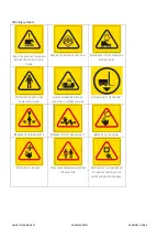
Page 6: ...AFETY FOOTWEAR AND WORK GLOVES DO NOT WEAR ANY LOOSE ITEMS OF CLOTHING ALWAYS GRAB THE PIECE OF WOOD OR LOG FROM THE SIDE LIFTING POINT FOR FORKLIFT BEWARE OF MOVING PARTS BEWARE OF THE CARDAN SHAFT B...

Page 7: ...THE MACHINE RISK OF CRUSHING THE MAXIMUM PERMITTED ANGLE OF THE CONVEYOR IS 40 DO NOT PASS UNDER THE CONVEYOR THE MAXIMUM SPEED FOR THE CARDAN SHAFT IS 410 RPM THE ROTATION DIRECTION IS IN THE DIRECTI...

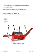
Page 8: ...s not sustained any damage during transit and ensure that all necessary parts are included in the package In the event of any defects or damage contact the retailer immediately 2 2 MAIN COMPONENTS OF...

Page 9: ...ranging the machine for operation ensure that the operating conditions detailed in Section 1 4 are met and review the safety instructions in Section 1 5 Note Inspect and clean the machine before setti...

Page 10: ...pin A and turning locking latch B out of its slot Figure 3 Note At the same time hold the end of the input conveyor with your left hand Figure 4 4 Lower the input conveyor with your left hand while si...

Page 11: ...sufficient room for opening the output conveyor 2 Turn off the machine and disconnect it from the power source 3 Keep lock A Figure 5 open and lower the output conveyor using a winch to its lowest po...

Page 12: ...lower the conveyor to the lowest possible position with the winch 3 Turn support bar C Figure 7 to a position over the belt and turn the upper section of the con veyor onto the lower section using ha...

Page 13: ...ure 9 When using the cardan shaft observe any instructions provided by the manufacturer of the shaft The ma chine requires 5 5 kW of power which must be taken into account with regard to the capacity...

Page 14: ...ction of the machine Use the red button to turn off the machine If the electric motor rotates in the wrong direction i e the machine makes an abnormal noise and the hy draulic functions are inoperable...

Page 15: ...no one in the tractor cabin so as to prevent any accidental contact with the controls Check all the connecting devices of the tractor and the firewood processor before connecting them Never use fault...

Page 16: ...otating the valve adjustment screw clockwise slows down the speed of the in feed convey or belt in relation to the splitting cycle and vice versa The control valve is only needed when the machine is e...

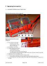
Page 17: ...ver C Cutting and splitting control lever The splitting beam moves forward by pushing the lever up This also moves the input conveyor forward The splitting beam moves backwards by pulling the lever do...

Page 18: ...equirements listed above are not met 3 2 PERFORMING A TEST RUN ON THE MACHINE 1 Check that the guard for the firewood processor s cutting and splitting section is down 2 Check that the input and outpu...

Page 19: ...clothes hands or other parts getting caught in the machine such as due to the shape of the log Do not use your hand to guide the log into the cutting section Adjust the measuring device to the desired...

Page 20: ...input table with a loader is strictly prohibited Note Ensure that the log s centre of gravity stays on the conveyor Sawing the last log When sawing wood the second to last piece should be sawn in such...

Page 21: ...SION 1 2015 Figure 16 Figure 17 If the conveyor is jammed for any reason the machine must be shut down before removing the cause There must be at least 50 cm between the end of the output conveyor and...

Page 22: ...carry out any maintenance 8 Store the machine according to the instructions in Section 4 13 4 Maintenance and adjustment of the machine The machine must be disconnected from its power source before m...

Page 23: ...e protective cover of the machine 2 Set the wood limiter in the splitting section to the desired length by removing cotter pin B from the limiter s locking pin and pulling out locking pin A Figure 18...

Page 24: ...ng knife can be raised by moving lever D Figure 15 to the left and vice versa as indicated by the label in Figure 21 Logs should always be as centred as possible when passing the knife in order to kee...

Page 25: ...otective gloves 1 Remove any firewood under the splitting knife and lower it to the lowest position using lever D Figure 15 as shown in Figure 22 2 Turn off the machine and disconnect it from its powe...

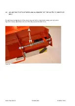
Page 26: ...4 5 ADJUSTING THE TIGHTNESS AND ALIGNMENT OF THE OUTPUT CONVEYOR BELT The tightness and alignment of the output conveyor belt can be adjusted using nuts A 2 pcs in Figure 23 Loosen adjustment nuts A o...

Page 27: ...saw bar bolts B Figure 24 4 Fully loosen adjustment screw A for saw chain tension Figure 24 5 Remove the old saw chain 6 Install the new saw chain and ensure that the cutting teeth come first in rela...

Page 28: ...g the saw chain 2 Remove the saw bar bolts 2 pcs and remove fastening plate A Figure 27 3 Remove the saw bar from the groove 4 Place the new bar against gear wheel B Figure 27 twist it into the groove...

Page 29: ...the hydraulic oil tank in Figure 28 this will allow the oil to drain more easily 3 Open drain plug B Figure 29 and drain the oil into a suitable contain er 4 Open the hydraulic filter cover C Figure 2...

Page 30: ...litres of appropriate oil to the angle transmission through the breather opening The multiplier gear is small so approx 1 dl of oil is suffi cient 6 Finally close breather cap A Figure 30 Figure 30 4...

Page 31: ...ead the rest of the belt under the wood gripper around the rear roller and finally behind the conveyor 8 Connect the joint by inserting pin A Figure 31 into the joint Figure 33 9 Turn the conveyor bac...

Page 32: ...The belt is at the correct tension when its middle section is raised approx 15 cm when the conveyor is in the operating position An excessively tight belt may be damaged more easily and it places unn...

Page 33: ...HAKKI PILKE RAVEN TRANSLATION VERSION 1 2015 Figure 35 Figure 36 Figure 37 Figure 38 Figure 39 Figure 40 Figure 41 Figure 42...

Page 34: ...HAKKI PILKE RAVEN TRANSLATION VERSION 1 2015 Figure 43 Figure 44 Figure 45 Figure 46 Figure 47...

Page 35: ...e added when there is approx 5 cm of oil left in the canister Detach the protective cover of the canister by removing locking screw D Figure 47 and lifting the protective cover using open ing C Note I...

Page 36: ...to operate The relief valve adjustments can be changed as follows loosen the locking nut or remove the protective cup and rotate the hex socket screw clockwise or anti clockwise when turning the screw...

Page 37: ...a level and solid foundation Although the machine is intended for outdoor use it should be covered and stored in a sheltered location or indoors Before prolonged stor age the machine must first be cl...

Page 38: ...or belt The output conveyor does not move The belt is too loose The output conveyor s relief valve is leaking Tighten the belt in accord ance with the instructions in Section 4 5 Replacing and tighten...

Page 39: ...ammed on the splitting knife in a situation where the splitting force is insufficient to push the piece past the knife despite several attempts to do so do the following Return the splitting cylinder...

Page 40: ...HAKKI PILKE RAVEN TRANSLATION VERSION 1 2015 6 Hydraulics diagram tractor operated machine...

Page 41: ...the sell er or the manufacturer Repair under guarantee requires that the customer can reliably prove that the guarantee is valid 5 The guarantee does not include standard adjustments user guidance ca...

Page 42: ...nd Name and address of the person who is authorised to compile the technical file Name Tapio Aittokoski Address Valimotie 1 FI 85800 Haapaj rvi Finland The aforementioned person assures that Hakki Pil...

Reviews: