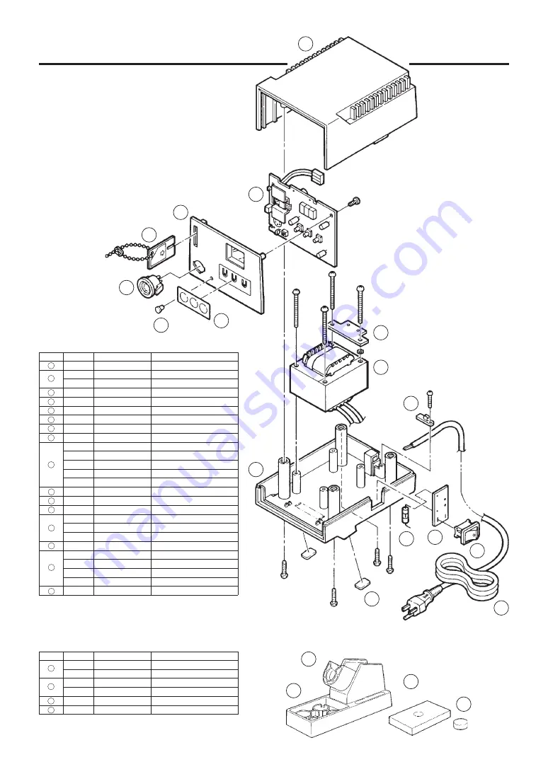
background image

15. PARTS LIST

16

12

10

14

16

13

11

15

8

9

7

5

6

3

2

4

1

2

1

3

4

Item No.

1

2

3

4

5

6

7

8

9

10

11

12

13

14

15

16

Part Name

Upper Case

P.W.B. for temp. control

P.W.B. for temp. control

Panel

Receptacle

Card

CAL Pot Plug

Membrane sheet

Grounding Plate

Transformer

Transformer

Transformer

Transformer

Transformer

Lower Case

Cord Stopper

Power switch

Fuse/2A

Fuse/2A

Fuse/0.8A

Rubber Stopper

Power Cord

Power Cord

Power Cord

Power Cord

Wiring Board for Switch

Specifications

E.S.D.

Australia

100-24V

110-24V

120-24V (UL)

220-240-24V

240-24V (Australia)

E.S.D., with rubber stopper

100, 110V

120V (UL)

220-240V

set of 2

3 core but no plug

3 core & American plug

3 core & Australian plug

3 core & European plug

Part No.

B2034

B2036

B2322

B2035

B2006

B2037

B2018

B2047

B2227

B2038

B2039

B2040

B2041

B2302

B2002

B2015

B1084

B2007

B2224

B2008

B2016

B1318

B1319

B2042

B2043

B2103

Item No.

1

2

3

4

Part No.

C1141

C1142

B2020

B2021

B2019

A1042

Part Name

Iron Holder

Iron Holder

Iron Receptacle

Iron Receptacle

Iron Holder Base

Cleaning Sponge

For

900S

907, 908

900S

907, 908

900S, 907, 908

900S, 907, 908

Station

Iron holder

Binding Head Tapping Screw
M3.5 

×

 45 (4)

Tapping Screw
M2.6 

×

 8 (1)

Tapping Screw
M3 

×

 12 (1)

Tapping Screw
M4 

×

 12 (4)

Summary of Contents for 937

Page 1: ...ade by another manufacturer is used the original performance of the soldering iron may not be obtained Furthermore the heating element P W B and transformer may be damaged TABLE OF CONTENTS 1 PACKING...

Page 2: ...m 4 ft 176 mm 7 in 25 g 0 06 lbs 908 ESD 200 mm 7 9 in 54 g 0 12 lbs 907 ESD 190 mm 7 5 in 44 g 0 09 lbs 2 SPECIFICATIONS Name Power Consumption HAKKO 937 60W Part Name Output Voltage Temperature Ran...

Page 3: ...considered potentially dangerous Turn the power off while taking breaks and when finished using the unit Before replacing parts or storing the unit turn the power off and allow the unit to cool to ro...

Page 4: ...tip A Iron holder 1 Small cleaning sponge Dampen the small cleaning sponge with water and then squeeze it dry Place it in one of the 4 openings of the iron holder base 2 Add water to approximately th...

Page 5: ...ight in Turn clockwise firmly CAUTION Be sure to insert the correct end of the card into the card slot While setting the temperature the heating element is off Press or Insert the card Press once C Se...

Page 6: ...one second the present temperature setting will be displayed for two seconds then the display will again show the tip temperature 1 After setting the temperature remove the card The preset temperature...

Page 7: ...parameter is entered in the same manner as used to set the temperature see pg 4 5 steps 2 4 Be sure to use a value within the allowable range see chart at left If a value outside this range is selecte...

Page 8: ...hold down the and buttons simultaneously and turn the power switch on see Parameters on pg 6 3 Following the procedure on page 6 display the room temperature compensation value test mode This is the m...

Page 9: ...4D 900M T 3 2D 900M T 1 2LD 900M T SB 900M T B 900M T LB 900M 0 5C 900M 0 8C 900M T 1C 900M T 1CF 900M T 1 5CF 900M T 2C 900M T 2CF 900M T 3C 900M T 3CF 900M T 4C 900M T 4CF 900M T K 900M T R 900M T...

Page 10: ...east once a week This helps prevent seizure and reduction of the tip temperature Never leave the soldering iron sitting at a high temperature for long periods as the tip s solder plating will become c...

Page 11: ...0 008 0 08 2 17 0 66 R0 5 0 02 25 0 98 R0 2 0 008 15 0 6 0 02 0 5 17 0 66 0 031 0 8 15 0 6 0 04 1 15 0 6 0 06 1 5 17 0 66 0 08 2 17 0 66 0 1 3 0 1 3 17 0 66 0 16 4 0 16 4 15 0 6 0 2 5 2 0 08 17 0 66...

Page 12: ...is being sent to the soldering iron and the tip temperature goes below the heater error temperature tolerance setting the temperature display will begin flashing on and off This indicates a possible...

Page 13: ...ting plug disconnected Connect it Is the soldering iron cord broken See Check for a broken heating element or cord assembly pg 14 Is the heating element broken See Check for a broken heating element o...

Page 14: ...oxide Clean the tip See Tip care and use pg 9 Is the iron calibrated correctly Recalibrate see Tip care and use pg 9 Contact your nearest HAKKO representative Is the tip too small for the items to be...

Page 15: ...and the cord assembly 11 out of the handle 12 Toward the tip of the iron 4 Pull the grounding spring 5 out of the sleeve Heating Element Red Sensor Blue Measure when the heating element is at room te...

Page 16: ...th including in the strain relief area If the LED heater lamp flickers then the cord needs to be replaced 2 Check the resistance between the pin of the plug and the wire on the terminal Pin 1 Red Pin...

Page 17: ...24V 120 24V UL 220 240 24V 240 24V Australia E S D with rubber stopper 100 110V 120V UL 220 240V set of 2 3 core but no plug 3 core American plug 3 core Australian plug 3 core European plug Part No B2...

Page 18: ...07 908 For 907 908 907 908 907 908 907 908 907 908 Specifications See page 10 See page 10 Part Name Nut Nut Tip Enclosure Tip Enclosure Soldering Tip Soldering Tip Nipple Nipple Grounding Spring Part...

Page 19: ...18 16 WIRING DIAGRAM Control P W B Transformer Ground Power switch Switching P W B BLK WHT WHT BLK RED...

Page 20: ...2004 2 MA00110JN040219 19...

Reviews: