background image

6. PARAMETERS

The HAKKO 937 has three user-adjustable or viewable
parameters: a) Temperature display mode (Centigrade or
Fahrenheit), b) Heater-error temperature tolerance, and
c) Room temperature compensation value (test mode).
Once parameter-input mode is entered, these
parameters are set in the order shown. Once all three
parameters have been set, normal operation is resumed.

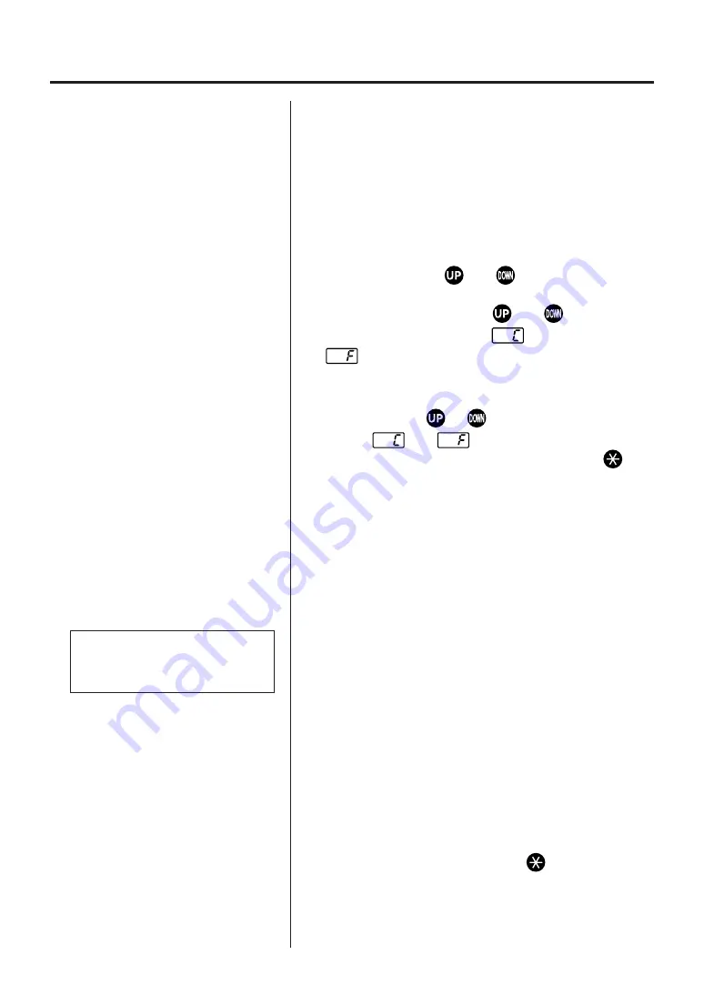
1. Turn off the power switch.

2. Press and hold the 

 and 

 buttons

simultaneously, and turn on the power switch.

3. Continue holding down the 

 and 

 buttons until

the display indicates either 

 (for Centigrade) of

 (for Fahrenheit). The station is now in

parameter input mode.

4. Press either the 

 or 

 button to alternately

display 

 and 

.

5. When the desired method is displayed, press 

.

The heater-error temperature will now be displayed
and the left-most digit (100’s digit) in the display will
begin flashing.

The heater-error temperature tolerance parameter is
entered in the same manner as used to set the
temperature. (see pg. 4, 5, steps 2-4.)

Be sure to use a value within the allowable range. (see
chart at left). If a value outside this range is selected, the
display will again flash the 100’s digit. Should this occur,
re-enter a correct value.

After setting the heater-error temperature tolerance, the
display will show the room temperature compensation
value (test mode).

This is the measured temperature of the soldering iron
tip. It is used to calibrate the tip temperature. (see pg. 7,
Calibration of iron temperature)

No inputs are made here. The display will not blink nor

will the heater receive power. Press 

 to complete

parameter input. The soldering temperature setting will
be displayed for two seconds, then power will be
supplied to the heater and normal temperature control
will begin.

Heater-error temperature range

Centigrade: 30 - 150

°

C

Fahrenheit: 60 - 300

°

F

6

Parameter input mode

1. Centigrade or Fahrenheit

temperature display

2. Heater-error temperature

tolerance
(see Heater error on page 11)

3. Room temperature

compensation value
(test mode)

Summary of Contents for 937

Page 1: ...ade by another manufacturer is used the original performance of the soldering iron may not be obtained Furthermore the heating element P W B and transformer may be damaged TABLE OF CONTENTS 1 PACKING...

Page 2: ...m 4 ft 176 mm 7 in 25 g 0 06 lbs 908 ESD 200 mm 7 9 in 54 g 0 12 lbs 907 ESD 190 mm 7 5 in 44 g 0 09 lbs 2 SPECIFICATIONS Name Power Consumption HAKKO 937 60W Part Name Output Voltage Temperature Ran...

Page 3: ...considered potentially dangerous Turn the power off while taking breaks and when finished using the unit Before replacing parts or storing the unit turn the power off and allow the unit to cool to ro...

Page 4: ...tip A Iron holder 1 Small cleaning sponge Dampen the small cleaning sponge with water and then squeeze it dry Place it in one of the 4 openings of the iron holder base 2 Add water to approximately th...

Page 5: ...ight in Turn clockwise firmly CAUTION Be sure to insert the correct end of the card into the card slot While setting the temperature the heating element is off Press or Insert the card Press once C Se...

Page 6: ...one second the present temperature setting will be displayed for two seconds then the display will again show the tip temperature 1 After setting the temperature remove the card The preset temperature...

Page 7: ...parameter is entered in the same manner as used to set the temperature see pg 4 5 steps 2 4 Be sure to use a value within the allowable range see chart at left If a value outside this range is selecte...

Page 8: ...hold down the and buttons simultaneously and turn the power switch on see Parameters on pg 6 3 Following the procedure on page 6 display the room temperature compensation value test mode This is the m...

Page 9: ...4D 900M T 3 2D 900M T 1 2LD 900M T SB 900M T B 900M T LB 900M 0 5C 900M 0 8C 900M T 1C 900M T 1CF 900M T 1 5CF 900M T 2C 900M T 2CF 900M T 3C 900M T 3CF 900M T 4C 900M T 4CF 900M T K 900M T R 900M T...

Page 10: ...east once a week This helps prevent seizure and reduction of the tip temperature Never leave the soldering iron sitting at a high temperature for long periods as the tip s solder plating will become c...

Page 11: ...0 008 0 08 2 17 0 66 R0 5 0 02 25 0 98 R0 2 0 008 15 0 6 0 02 0 5 17 0 66 0 031 0 8 15 0 6 0 04 1 15 0 6 0 06 1 5 17 0 66 0 08 2 17 0 66 0 1 3 0 1 3 17 0 66 0 16 4 0 16 4 15 0 6 0 2 5 2 0 08 17 0 66...

Page 12: ...is being sent to the soldering iron and the tip temperature goes below the heater error temperature tolerance setting the temperature display will begin flashing on and off This indicates a possible...

Page 13: ...ting plug disconnected Connect it Is the soldering iron cord broken See Check for a broken heating element or cord assembly pg 14 Is the heating element broken See Check for a broken heating element o...

Page 14: ...oxide Clean the tip See Tip care and use pg 9 Is the iron calibrated correctly Recalibrate see Tip care and use pg 9 Contact your nearest HAKKO representative Is the tip too small for the items to be...

Page 15: ...and the cord assembly 11 out of the handle 12 Toward the tip of the iron 4 Pull the grounding spring 5 out of the sleeve Heating Element Red Sensor Blue Measure when the heating element is at room te...

Page 16: ...th including in the strain relief area If the LED heater lamp flickers then the cord needs to be replaced 2 Check the resistance between the pin of the plug and the wire on the terminal Pin 1 Red Pin...

Page 17: ...24V 120 24V UL 220 240 24V 240 24V Australia E S D with rubber stopper 100 110V 120V UL 220 240V set of 2 3 core but no plug 3 core American plug 3 core Australian plug 3 core European plug Part No B2...

Page 18: ...07 908 For 907 908 907 908 907 908 907 908 907 908 Specifications See page 10 See page 10 Part Name Nut Nut Tip Enclosure Tip Enclosure Soldering Tip Soldering Tip Nipple Nipple Grounding Spring Part...

Page 19: ...18 16 WIRING DIAGRAM Control P W B Transformer Ground Power switch Switching P W B BLK WHT WHT BLK RED...

Page 20: ...2004 2 MA00110JN040219 19...

Reviews: