No.A1560
中文
English
日本文
No.A1560
中文
English
日本文
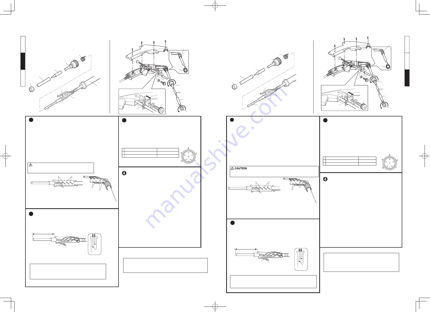
Be sure to remove the nut before removing the nipple. Removing the nipple
first could cause the heater leads to twist and cause a short circuit.
Resistance
value of
heating element
Resistance value
of sensor
NOTE :
終端板
更換發熱元件
�. 將發熱元件引線和傳感器引線除鍚,除下發熱元件,然後更換新的。
●
部
件名稱
更換發熱元件方法
檢查發熱元件
1
發熱元件電阻值
傳感器電阻值
發熱元件引線(紅色)
2
��毫米
扭彎成直角形
拉直引線
發熱元件
引線
紅
更換及回裝後的檢查
更換後
�. 測量第�插針和第�及第�插針之間;
第 � 插針和第 � 及第 � 插針之間電阻值。如果不是∞(無限大),
則是發熱元件和傳感器發生了接觸。
�. 測量“a”“b”“c”電阻值以確定引線沒有被扭曲,
而接地彈簧也連接妥當。
3
a
b
c
第�腳與第�腳之間(發熱元件)
第�腳與第�腳之間(傳感器)
第�腳與焊鐵頭之間
�.�-�.�歐姆(正常)
��-��歐姆(正常)
�歐姆以下
重新校準溫度
為確保焊接溫度的准確性,更換發熱元件後,要重新校準溫
度。將焊鐵連接到電焊台。
※ 順時針方向旋轉溫度校準計,以提高焊鐵頭溫度,反時針方向
為降溫。
※ 校準HAKKO FX-���之前必須先除下CAL用蓋。
※ 焊鐵頭溫度之測定,請使用溫度計或焊鐵測試器。
注記:
需要維修時,請將焊鐵及電焊台一併送去您的銷售商檢修。
※上述規格可能變更,怒不另行奉告。
※本產品有防靜電處理。
●
Part Names
Replacing the Heating Element
2
3
Recalibrate the temperature
To ensure accurate soldering temperatures, always calibrate
the temperature after replacing the heating element.
Connect your iron/gun to the station for calibration.
* Turn the temperature calibrator clockwise to increase the
temperature and counterclockwise to reduce the temperature.
* Remove the CAL pot plug before calibrating HAKKO FX-888.
* We recommend the Thermometer or Soldering tester for
measuring the tip temperature.
Handle
Sleeve
Heating element
Glass tube
Terminal board
Nut
Tip enclosure
Tip
Nipple
Grounding spring
Checking the heating element
●
Soldering iron
1
Resistance Value
of Heating Element
Resistance Value
of Sensor
Heating Element Leads (Red)
Replacing the heating element
1. Desolder the heating element leads and sensor leads.
Remove the heating element and replace it with a new one.
●
There is no polarity between leads of the same color.
●
Adjust the length of the heating element so that length from
end of the terminal board to end of the heating element is 64 mm.
Heating
element
lead
Red
64mm (2.52in)
Straighten the tube.
Bend at right angle.
Inspection after replacement
and reassemble
After replacing the heating element,
1. Measure the resistance value between pins 4 & 1, 4 & 2,
pins 5 & 1 and 5 & 2. If it is not
∞
, the heating element and
sensor are touching.
2. Measure the resistance value ‘a’, ‘b’, and ‘c’ to confirm that
the leads are not twisted and that the grounding spring is
properly connected.
c Between pin 3 & Tip
a Between pins 4 & 5 (Heating Element) 2.5 - 3.5
Ω
(Normal)
b Between pins 1 & 2 (Sensor)
43 - 58
Ω
(Normal)
Under 2
Ω
When repairs are needed, please send both the soldering iron
and the station to your sales agent.
*Specifications subject to change without notice.
*This product is protected against electrostatic discharge.
Nut
Tip enclosure
Tip
Nipple
Grounding
spring
Adjusting
screw
Supporting fitting
Glass tube
1. Turn the nut counterclockwise and remove the tip enclosure and the tip.
2. Turn the nipple counterclockwise and remove it from the iron.
3. Pull both the heating element and the cord assembly
out of the handle. (Toward the tip of the iron.)
4. Pull the grounding spring out of the sleeve of the terminal.
1. Remove the adjusting screw and keep the support fitting apart
from the housing.
2. Turn the nut counterclockwise and remove the tip enclosure and tip.
3. Turn the nipple counterclockwise and remove it from the gun.
4. Remove the 4 screws and open the housing.
5. Pull the grounding spring out of the sleeve.
●
Soldering gun
Measure when the sensor and heating element is at room temperature.
1. Heating element resistance (red) 2.5-3.5
Ω
2. Sensor resistance (blue) 43-58
Ω
If the resistance value is not normal, replace the heating element.
If the resistance value is normal, the cord assembly may be broken.
2. Solder the leads, and then cut extra leads after cooled down.
Pass the leads through the terminal board, push the lead down inside the
terminal board, then solder it. Be sure leads are covered by glass tube.
Cut the wire to leave no more than 1 to 2 mm from the solder joint.
●
Solder in the joints must be visible from both sides of the terminal board.
1. Set the temperature control knob to 350°C(662°F).
2. Turn the power switch to “ON” and wait until the temperature
stabilizes. Remove the CAL pot plug.
3. When the iron tip temperature stabilizes, measure the tip
temperature using an tip thermometer. As necessary,
fit the included CAL adjustment driver in the hole
in the station indicated by the CAL marking, and
make adjustments so that the tip temperature is 350°C(662°F).
NOTE:
�. 取出調整螺絲,將固定板從機身解開。
�. 向反時針方向扭開螺帽,除下鋼管和焊鐵頭。
�. 向反時針方向扭開套頭,從焊鐵中拉出套頭。
�. 取出 � 個螺絲打開機身。
�. 從套管中拉出接地彈簧。
※請在室溫時測量傳感器及發熱元件。
�. 發熱元件電阻值(紅色)�.�~�.�Ω
�. 傳感器電阻值(藍色)��~��Ω
如果電阻值反常,更換發熱元件。
如果電阻值是正常的,則電線組件可能破裂。
●焊鐵
●焊鐵連出錫裝置
必須取出螺帽之後才取出套頭。如果先取出套頭,
發熱元件之引線會被扭曲,可能引起短路。
注意
傳感器電阻值
發熱元件電阻值
調節螺絲
固定板
套頭
焊鐵頭
鋼管
螺帽
接地彈簧
螺帽
鋼管
焊鐵頭
套頭
接地彈簧
發熱元件
手柄
D形套
�. 將溫度調節旋鈕設定為 ���°C。
�. 按下電源開關,靜候溫度達到穩定為止。
取下 CAL 用蓋。
�. 若焊鐵頭溫度已穩定,便使用焊鐵頭溫度計測定焊鐵頭溫度。
將附屬的 CAL 調整用起子插入機座上之 CAL 孔內,
調節溫度直到焊鐵頭溫度達到 ���°C為止。
玻璃管
玻璃管
�. 向反時針方向扭開螺帽,除下鋼管和焊鐵頭。
�. 向反時針方向扭開套頭,從焊鐵手柄拉出套頭。
�. 向焊鐵頭方向將發熱元件及連接線組從手柄拉出。
�. 從終端板的套管中拉出接地彈簧。
●相同顏色引線之間,不分極性。
●調整發熱元件距離直至終端板頂端與發熱元件之間距離��毫米。
�. 焊接引線,待冷卻後剪去多餘引線 。
注記:
將引線穿過終端板,將引線推向終端板內側,然後焊接引線。
請確認玻璃管完全套住引線。
離焊接點不多於�-�毫米之處剪去多餘的引線。
●焊鍚量以從終端板兩面能看到為宜。
焊鐵
焊鐵連出錫裝置
Soldering iron
Soldering gun
A1560_JEC_WIN_200916.indd 2
A1560_JEC_WIN_200916.indd 2
2020/09/16 10:34:05
2020/09/16 10:34:05


