First Edition: March 31, 2007
2-6 Inspection after Repair (FX-951/FH-200)
2-6
Inspection after Repair
Perform the inspection after repair.
<Preparations>
W-I tester / DMM (Tester) / Power meter (or ammeter) / Thermo-couple
thermometer (HAKKO192)
(1) Voltage application test
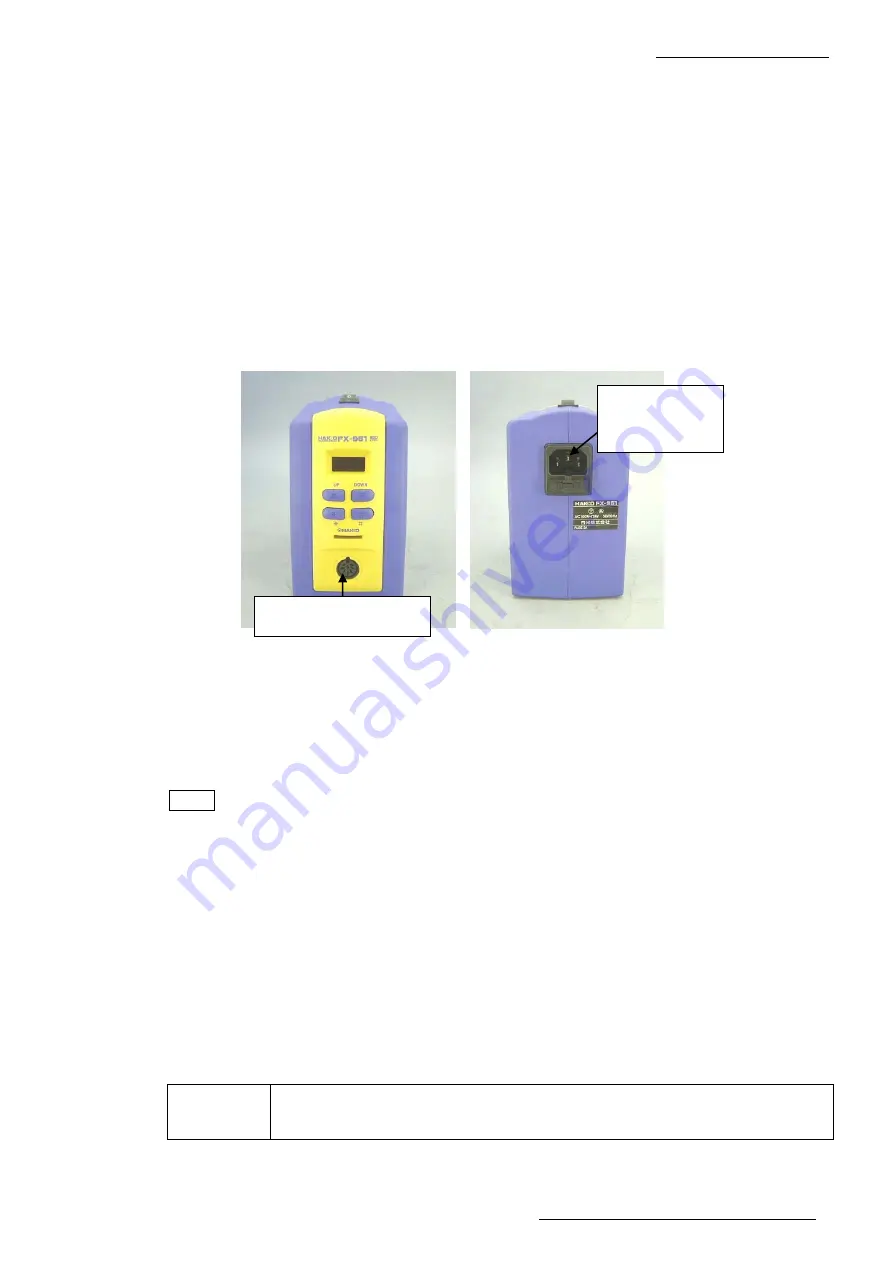
Resistance between power receptacle ground terminal and receptacle pin 2 (for
measurement point, refer to the photo) is 1
Ω
or lower.
Resistance between power receptacle ground terminal and IRON 2 receptacle pin 2 is 1
Ω
or lower.
(2) Insulation test and withstanding voltage test
[Insulation test] Apply 500VDC and check that the value is 25M
Ω
or higher.
[Withstanding voltage test] Apply 1250VAC (1mA) to check that it can resist for 1 second or
longer.
NOTE
Perform the following inspections with a proper tip.
(3) Check the power consumption.
Power consumption must be 75W ±10%.
(4) Measure the tip-to-ground potential and the tip to ground resistance.
The tip-to-ground potential must be 1mV or lower.
The tip to ground resistance must be 1.0
Ω
or less.
(5) Check the temperature.
The tip temperature must be at the setting temperature ±15°C.
CAUTION
If an accessory iron is provided, return it to a customer with lead-free
solder put on the tip. (To prevent oxidation)
Pin 2: Center at bottom
Power receptacle
grounding
terminal


