First Edition: March 31, 2007
2-4 Voltage Application Check (FX-951/FH-200)
2-4
Voltage Application Check
Perform a voltage application check.
NOTE
Without attaching the iron, perform a check with the following procedures.
(1) Check the soldering iron error.
1. Turn on the power switch.
2. The following indications appear on the display in the order presented, and the
buzzer keeps beeping.
3. Turn off the power switch.
If no indication appears on the display:
The P.W.B. is faulty. Check the P.W.B. using the procedure in step (7).
When an indication appears on the display but it does not function properly:
The P.W.B. is faulty. Check the P.W.B. using the procedure in step (7).
NOTE
Connect the iron (without the tip) and check according to the following procedures.
(2) Check the sensor errors.
1. Turn on the power switch.
2. The following indications appear on the display in the order presented, and the
buzzer keeps beeping.
3. Turn off the power switch.
If no indication appears on the display:
The P.W.B. is faulty. Check the P.W.B. using the procedure in step (7).
When an indication appears on the display but it does not function properly:
The P.W.B. is faulty. Check the P.W.B. using the procedure in step (7).
NOTE
Connect the iron (without the tip) and check according to the following procedures.
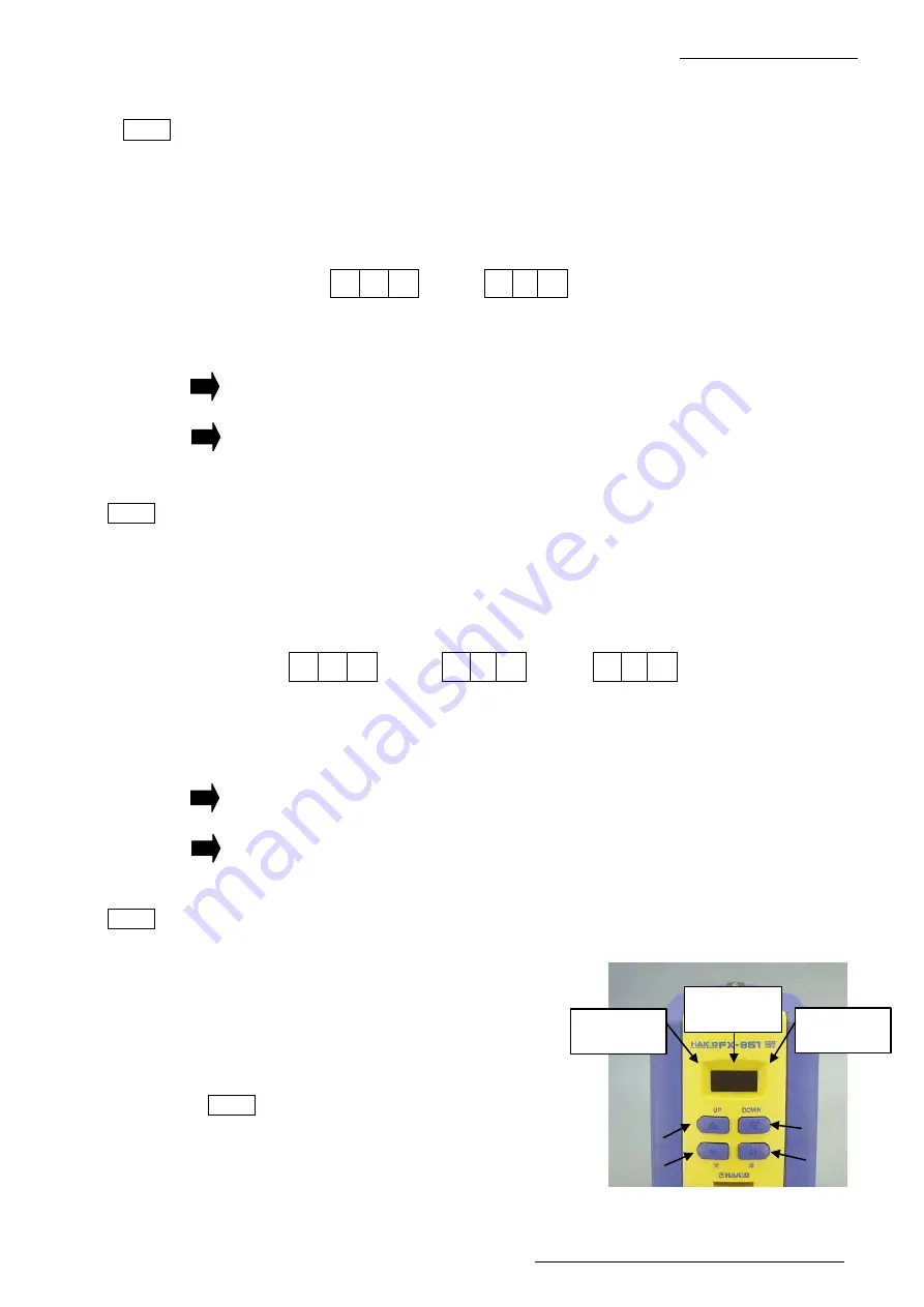
(3) Check the LCD.
1. Insert a card.
2. While holding down the four operation
buttons, turn on the power switch.
3. After the version No. (ex. [001]) is
displayed, the segment of the indicator
[Left] will be lit sequentially.
NOTE
The figures to be displayed vary
depending on the version of P.W.B.
8. 8. 8.
C - E
→
Flashing
[Left]
3rd digit
[Right]
1st digit
[Center]
2nd digit
[UP]
[DOWN]
[*]
[#]
8. 8. 8.
3 5 0
→
S - E
→
(The example shows a
setting at 350
◦
C.)
Setting temperature
Flashing


