background image


��������������

���

���

���

��

������

������

�����

����������

������

�����������������������

���

���

���

����������

��

������

������

������

�����

�����������������������

���

��������

��

�����

������

������

�����������������������

������

���

���

���

��

�����

������

������

����������

������

�����������������������

���

��

���

���

�����

������

������

������

����������

�����������������������

���

���

���

���������

��

�����

������

������

������

���������������������

���

���

����

���������

��

������

������

����

������

����������������������

���

����

��

���

������

������

������

����������

������

����������������������

���

���

����

��

������

������

������

����������

������

����������������������

���

���

��

����

���������

������

������

������

������

����������������������

���

����

��

���

������

������

������

���������

������

����������������������

����

������

������

����������

����������

�����

�����������������������

����

���

���

������

������

������

����������

������

�����������������������

����

��

���

����������

��

������

������

������

������

�����������������������

����

���

���

������

������

����������

������

������������������������

����������

���

��

������

���������

��������

���������

������

������������������������

���

������

���������

��������

���������

��������

������������������������

���

������

����������

����������

����������

����������

������������������������

���

������

����������
����������

����������

���������

������������������������

�����

����������
����������

����������

����������

�����������������������

���

������

����������

��������

����������

��������

������������������������

���

���

��

��

������

���

������

������

������

������

����������������������

���

��

����

���

������

������

������

����������

������

����������������������

���

��

��

��

����������������������

������

������

������

���

����

������

������

������

���������������������

���

����

��

��

����������������������

������

������

������

14

1

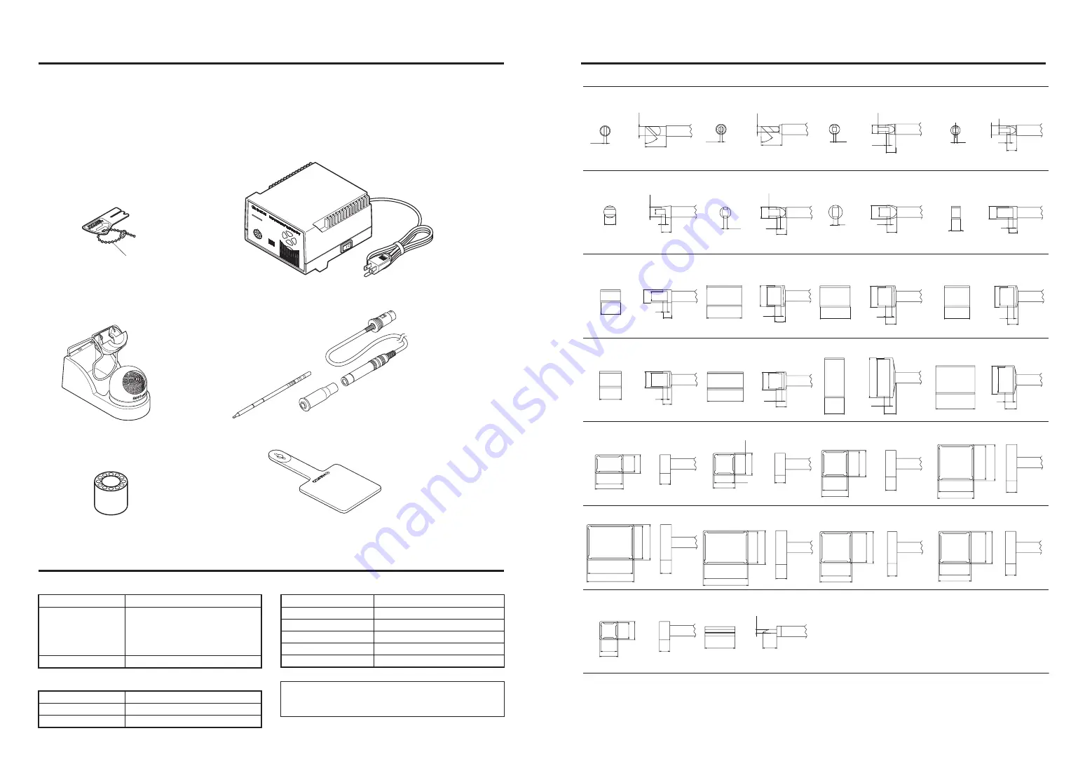
Heat resistant pad

Iron holder

FP-102 Soldering station

Control card

Card chain

Tip tray

Tip (not included)

FM-2021 Connector assembly

Sleeve assembly*

7.5

6.5

8.0

7.0

MOD

EL

FP-1

02

*Yellow, orange or blue sleeve 

assembly is included.

1. PACKING LIST


FP-102 soldering station .................................1

FM-2021 connector assembly .........................1 

Sleeve assembly ............................................ 1

Control card, with chain ...................................1

Heat resistant pad ...........................................1

Tip tray .............................................................1

Iron holder .......................................................1

Cleaning wire ...................................................1

Instruction manual ...........................................1

2. SPECIFICATIONS

 FP-102 Soldering Station

Power Consumption
Temperature Range

Temperature Stability

75 W
The four segment lights on the front 

panel indicate the heat range selected 

for the FP-102 (6.5 = ~650°F. [343°C]; 

7.0 = ~700°F. [371°C]; 7.5 = ~750°F. 

[399°C]; 8.0 = ~800°F. [427°C]).
±9°F (±5°C) at idle temperature

Power Consumption
Tip to Ground Resistance
Tip to Ground Potential
Total Length (w/o cord)
Weight (w/o cord)
Cord

70 W (24 V)
< 2 

< 2 mV
188 mm (7.4 in.) with 2.4D tip
30 g (0.067 lb./1.07 oz.) with 2.4D tip
1.2 m (4 ft)

 Soldering Iron

Output
Dimensions(W 

 H 

 D)

Weight (w/o cord)

24 V
120 

 93 

 140 mm (4.7 

 3.7 

 5.5 in.)

1,400 g (3.1 lb.)

 Station

NOTE:

This product is protected against electrostatic discharge.

Specifications and design are subject to change without notice.

Please check to make sure that all items listed below are includ-

ed in the FP-102 package.

Summary of Contents for FP-102

Page 1: ... CAUTIONS NOTES AND EXAMPLES 2 4 PART NAMES 3 5 INITIAL SETUP 3 6 OPERATION 5 7 PARAMETER SETTINGS 6 8 MAINTENANCE 7 9 ERROR MESSAGES 9 10 TROUBLE SHOOTING GUIDE 10 11 PARTS LIST 11 12 TIP STYLES 13 13 WIRING DIAGRAM 15 HEAD OFFICE 4 5 SHIOKUSA 2 CHOME NANIWA KU OSAKA 556 0024 JAPAN TEL 81 6 6561 3225 FAX 81 6 6561 8466 http www hakko com AMERICAN HAKKO PRODUCTS INC 28920 N AVENUE WILLIAMS VALENCI...

Page 2: ...Stability 75 W The four segment lights on the front panel indicate the heat range selected for the FP 102 6 5 650 F 343 C 7 0 700 F 371 C 7 5 750 F 399 C 8 0 800 F 427 C 9 F 5 C at idle temperature Power Consumption Tip to Ground Resistance Tip to Ground Potential Total Length w o cord Weight w o cord Cord 70 W 24 V 2 2 mV 188 mm 7 4 in with 2 4D tip 30 g 0 067 lb 1 07 oz with 2 4D tip 1 2 m 4 ft ...

Page 3: ...me wet or use it with wet hands Do not modify the FP 102 Use only genuine Hakko replacement parts Do not bend or damage the control card If the card does become damaged do not force the card into the station slot Do not strike the iron against hard objects to remove excess solder This may damage the iron Remove power and iron cords by holding theplug not thewires Be sure the work area is well vent...

Page 4: ...Holder 1 B3001 B2791 B2999 599B 02 599 029 B2756 With screw With rubber feet B3000 iron receptacle Iron receptacle Retaining clip Iron holder base Tip cleaner Cleaning wire Tip tray 3 2 1 1 6 1 2 3 7 6 5 4 3 1 3 5 See section 12 TIP STYLES 7 4 5 12 4 PART NAMES 3 Heat resistant pad Iron holder FP 102 Soldering station Control card Card chain Tip tray Tip cleaner Tip not included Receptacle Card sl...

Page 5: ...TE Spare or repair parts do not include mounting screws if they are not listed on the description Screws must be ordered separately 7 5 6 5 8 0 7 0 MODEL FP 102 FP 102 Station Item No Part No B2839 B2861 B2835B B2836 B2837 B2838 B2852 B1319 B2015 B2103 B2227 B2224 Part Name Control card Front panel P W B temperature control and connector Transformer Upper case Lower case Power switch Power cord Co...

Page 6: ...or one of the four seg ment buttons indicating the selected range will blink 3 When the set temperature is reached the buzzer alarm sounds indicating it is ready for use The indicator lamp remains on steadily NOTE When not in use place the soldering iron to the iron holder Control card Each FP 102 comes with a small card which inserts into the Card slot on the front of the unit This card is used w...

Page 7: ...tor lamps light in a slow clockwise sequence If the sta tion is left in this mode the alarm will continue to sound every thirty minutes To resume sol dering cycle the power switch OFF then ON The power will be turned on automatically if the heat range selector button is pressed before the temperature decreases to 100 C 212 F The auto power shutoff switch is on the bottom front of the case To turn ...

Page 8: ...emperature when sol dering The excellent thermal recovery charac teristics of the FP 102 ensure effective solder ing at low temperatures 2 Cleaning Always clean the soldering tip before use to remove any residual solder or flux adhering to it Use the 599B tip cleaner provided with the FP 102 or use a clean and moist cleaning sponge part no A1519 Contaminants on the tip have many deleterious effect...

Page 9: ...emperature when sol dering The excellent thermal recovery charac teristics of the FP 102 ensure effective solder ing at low temperatures 2 Cleaning Always clean the soldering tip before use to remove any residual solder or flux adhering to it Use the 599B tip cleaner provided with the FP 102 or use a clean and moist cleaning sponge part no A1519 Contaminants on the tip have many deleterious effect...

Page 10: ...tor lamps light in a slow clockwise sequence If the sta tion is left in this mode the alarm will continue to sound every thirty minutes To resume sol dering cycle the power switch OFF then ON The power will be turned on automatically if the heat range selector button is pressed before the temperature decreases to 100 C 212 F The auto power shutoff switch is on the bottom front of the case To turn ...

Page 11: ...or one of the four seg ment buttons indicating the selected range will blink 3 When the set temperature is reached the buzzer alarm sounds indicating it is ready for use The indicator lamp remains on steadily NOTE When not in use place the soldering iron to the iron holder Control card Each FP 102 comes with a small card which inserts into the Card slot on the front of the unit This card is used w...

Page 12: ...TE Spare or repair parts do not include mounting screws if they are not listed on the description Screws must be ordered separately 7 5 6 5 8 0 7 0 MODEL FP 102 FP 102 Station Item No Part No B2839 B2861 B2835B B2836 B2837 B2838 B2852 B1319 B2015 B2103 B2227 B2224 Part Name Control card Front panel P W B temperature control and connector Transformer Upper case Lower case Power switch Power cord Co...

Page 13: ...Holder 1 B3001 B2791 B2999 599B 02 599 029 B2756 With screw With rubber feet B3000 iron receptacle Iron receptacle Retaining clip Iron holder base Tip cleaner Cleaning wire Tip tray 3 2 1 1 6 1 2 3 7 6 5 4 3 1 3 5 See section 12 TIP STYLES 7 4 5 12 4 PART NAMES 3 Heat resistant pad Iron holder FP 102 Soldering station Control card Card chain Tip tray Tip cleaner Tip not included Receptacle Card sl...

Page 14: ...me wet or use it with wet hands Do not modify the FP 102 Use only genuine Hakko replacement parts Do not bend or damage the control card If the card does become damaged do not force the card into the station slot Do not strike the iron against hard objects to remove excess solder This may damage the iron Remove power and iron cords by holding theplug not thewires Be sure the work area is well vent...

Page 15: ...Stability 75 W The four segment lights on the front panel indicate the heat range selected for the FP 102 6 5 650 F 343 C 7 0 700 F 371 C 7 5 750 F 399 C 8 0 800 F 427 C 9 F 5 C at idle temperature Power Consumption Tip to Ground Resistance Tip to Ground Potential Total Length w o cord Weight w o cord Cord 70 W 24 V 2 2 mV 188 mm 7 4 in with 2 4D tip 30 g 0 067 lb 1 07 oz with 2 4D tip 1 2 m 4 ft ...

Page 16: ... CAUTIONS NOTES AND EXAMPLES 2 4 PART NAMES 3 5 INITIAL SETUP 3 6 OPERATION 5 7 PARAMETER SETTINGS 6 8 MAINTENANCE 7 9 ERROR MESSAGES 9 10 TROUBLE SHOOTING GUIDE 10 11 PARTS LIST 11 12 TIP STYLES 13 13 WIRING DIAGRAM 15 HEAD OFFICE 4 5 SHIOKUSA 2 CHOME NANIWA KU OSAKA 556 0024 JAPAN TEL 81 6 6561 3225 FAX 81 6 6561 8466 http www hakko com AMERICAN HAKKO PRODUCTS INC 28920 N AVENUE WILLIAMS VALENCI...

Reviews: