7.
CHECK PROCEDURE
2. Broken cord assembly
7. CHECK PROCEDURE
Resistance value
of heating element
Resistance value
of sensor
●
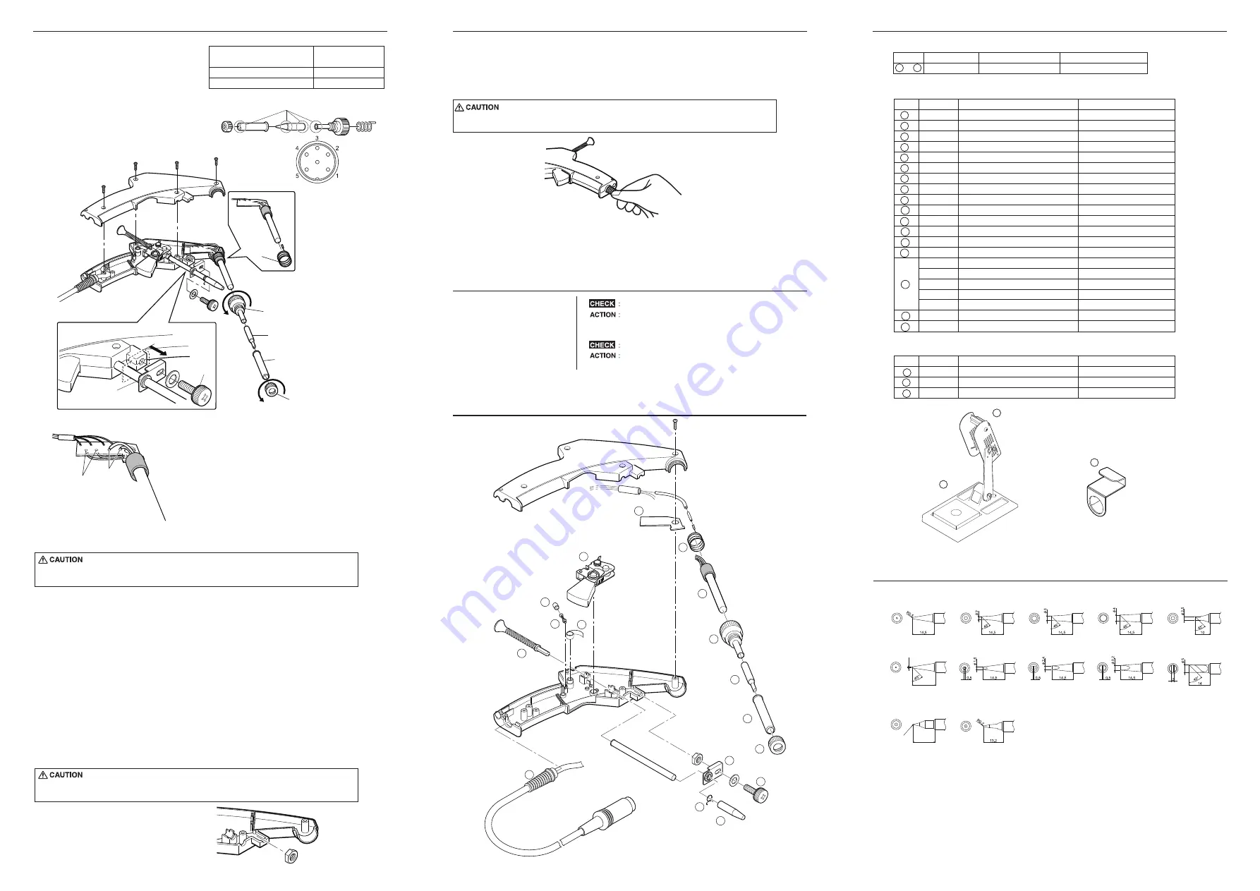
Soldering gun parts
●
HAKKO FX-8803
10. TIP STYLES
9. PARTS LIST
9. PARTS LIST
6
7
8
1
2
3
4
5
9
10
11
14
16
17
12
Hexagon nut M4
15
●
Option
1
2
3
13
●
●
There are two methods of testing the cord assembly as below.
1. Turn the power on and set the temperature control knob to 480℃. Then, bend the iron cord at
various locations along its length, including in the strain relief area.
If the LED heater lamp flashes, then the cord needs to be replaced.
2. Check the resistance between the plug pin and the terminal lead.
Pin 1: Red Pin 2: Blue Pin 3 : Green
Pin 4 : White Pin 5 : Black
If it is higher than 0 Ω or ∞, the cord should be replaced.
B2643
B2032
A1560
B2022
B3469
B1785
B2648
B2646
B2645
B2658
B2657
B3467
B1710
B2652
B2653
B2654
B2655
B2656
B2649
B2650
1
2
3
4
5
6
7
8
9
10
11
12
13
14
15
16
17
26V-65W
See “10.TIP STYLES”
With nut
0.6mm ESD
0.8mm ESD
1.0mm ESD
1.2mm ESD
1.6mm ESD
With grommet
For guide pipe
Terminal board
Grounding spring
Heating element
Nipple
Tip
Tip enclosure
Nut
Trigger set
Solder feed adjusting screw guide
Solder feed adjusting screw
Spring for trigger assembly
Solder inlet
Cord bushing
Nozzle securing ring
Guide nozzle
Guide nozzle
Guide nozzle
Guide nozzle
Guide nozzle
Support fitting
Adjudting screw
Item No. Part No.
Part Name
Specifications
FX8803-02
HAKKO FX-8803
1
〜
17
26V-65W
Part No.
Item No.
Part Name
Specifications
C1437
A1042
B2723
1
2
3
With cleaning sponge
With screw
Iron holder
Cleaning sponge
Hook
Part No.
Item No.
Part Name
Specifications
T18-B
T18-C2
T18-CF2 *
T18-C3
T18-CF3*
T18-C4
T18-CF4*
T18-CSF25*
T18-K
T18-D16
T18-D24
T18-D32
T18-S4
R0.125
14.5
T18-C08
15.5
φ0.8
T18-SB
* Tinned on the soldering surface only.
The power lamp starts to flash when the temperature reaches 480℃ regardless of the
condition of the cord.
8. TROUBLE SHOOTING GUIDE
Do you pull solder from a reel when using the trigger?
Do not pull solder from a heavy reel with the trigger.
Keep the solder loose (without tension) on the solder
inlet side at all times while soldering.
Is the solder inserted properly?
Refer to “1.Inserting the solder” under “5.OPERATION”.
●
Solder gets stuck
1. Broken heating element / sensor
Disconnect the plug of the cord assembly
and measure the resistance value
between the pin of the connecting plug as follows.
If the values of “a” and ”b” are outside
the value in the table, replace the heating
element(sensor) and/or cord assembly.
If the value of “c” is over the value in the
table, remove the oxidization film by lightly
rubbing with sand-paper or steel wool
the points shown in the drawing on the right.
a. Between pins 4 & 5
(heating element)
b. Between pins 1 & 2 (Sensor)
c. Between pin 3 & tip
2.5 ~ 3.5 Ω
(at time of room temperature)
43 ~ 58 Ω
2 or less Ω
Rub lightly with sand-paper or
steel wool.
Grounding
spring
Nipple
Tip
Tip enclosure
Nut
Support fitting
Adjusting
screw
1. Remove the adjusting screw and keep the support fitting apart from the housing.
2. Turn the nut counterclockwise and remove the tip enclosure and tip.
Be sure to remove the nut before removing the nipple. Removing the nipple first
could cause the heater leads to twist and cause a short circuit.
3. Turn the nipple counterclockwise and remove it from the gun.
4. Remove the 4 screws and open the housing.
5. Pull the grounding spring out of the sleeve.
*Measure when the heating element is at room temperature.
1. Heating element resistance (red) 2.5-3.5
Ω
2. Sensor resistance (blue) 43-58
Ω
If the resistance value is not normal, replace the heating element.
(Refer to the instructions included with the replacement part.)
After replacement
1. Measure the resistance between pins 4 and 1, 4 and 2, 5 and 1, and 5 and 2.
If it is not ∞, the heating element and sensor are touching. This will damage the circuit board.
2. Measure the resistance “a”, “b”, and “c” to confirm that the leads are not twisted and
that the grounding spring is properly connected.
When reassembling, be sure to match the convex part of the hexagon nut to concave
part of the housing.
Hexagon nut M4


