background image

4. INITIAL SETUP 

A. Setup the iron holder
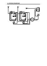
(1) Cleaning Sponge

1. Fit the small sponge pieces into the hollows of the 

iron holder base.

2. Add an appropriate amount of water into the iron 

holder base. The small sponge will absorb water 

and help keep the large sponge damp at all times.

3. Dampen the large sponge and place it on the iron 

holder base.

(2) Cleaning Wire

Place it in the iron holder as shown on the right. 

See “B. Using the cleaning wire” in section 

7. MAINTENANCE”.

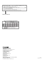
The angle of the iron receptacles is adjustable by 

changing the fastening position of the screws.

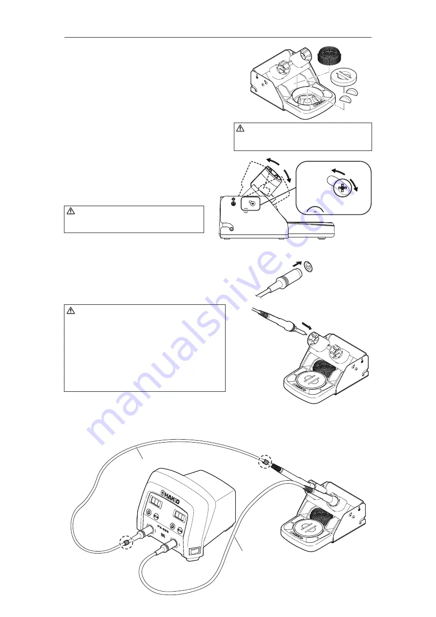
B. Connect the iron to the station

1. Connect the cord assembly to the receptacle.

2. Place the iron into the iron holder.

3. Plug the power cord into an appropriate power 

supply.

※ When using two soldering irons simultaneously

Attachment of the color bands to one of the soldering irons will help identify which soldering 

iron is connected to receptacle “A.IRON” and “B.IRON”.

(1)

(2)

CAUTION

Be sure the sponge is moistened with water

before use to avoid damaging the tip.

CAUTION

Increasing the angle of the iron receptacle will 

cause an increase in the iron grip temperature.

CAUTION

• Be sure to turn off the power before connecting or 

disconnecting the cord assembly for the iron to and 

from the receptacle to avoid damaging the circuit 

board.

• Do not use any iron other than those listed in Section 

1 of this manual. Doing so may result in inadequate 

performance and / or possible damage to the unit.

• The unit is protected against electrostatic discharge 

and must be grounded for full efficiency.

Push on the plug until

it stops, making sure it is

securely connected.

Receptacle

To disconnect, hold the plug

and pull it out of the receptacle.

With color bands

Without color band

Summary of Contents for FX-889

Page 1: ...AKKO FX 8801 Soldering iron M HAKKO FX 8802 Soldering iron N2 Type HAKKO FX 8803 Soldering gun HAKKO FX 8804 SMD Hot tweezer HAKKO FX 8805 Soldering iron L When using the HAKKO FX 8803 FX 8804 please...

Page 2: ...Failure to comply with a CAUTION may result in injury to the operator or damage to the items involved To prevent accidents or damage to the HAKKO FX 889 be sure to observe the following Do not use the...

Page 3: ...irons simultaneously Attachment of the color bands to one of the soldering irons will help identify which soldering iron is connected to receptacle A IRON and B IRON 1 2 CAUTION Be sure the sponge is...

Page 4: ...nd current temperature will be displayed When the display stabilizes the LED heater lamp will begin to flash B After use Always clean the tip and coat it with fresh solder after use Refer to Tip Maint...

Page 5: ...se refer to 6 PARAMETER SETTING CAUTION CAUTION How to distinguish between Temperature Setting Mode and Adjustment Mode The display differs in the temperature setting and the adjustment mode In the Te...

Page 6: ...screen for each mode after entering the password Please change the setting for each mode according to the procedure Enter the parameter setting to change the mode Please refer to 6 PARAMETER SETTING...

Page 7: ...f selecting the partial choose whether or not the password function is needed when moving to the temperature setting mode the preset mode and the adjust mode and set the password Parameter entering mo...

Page 8: ...tion 1 Press the button to change the display to 2 If you press the button the display will move to the setting mode selection screen If you press the button The normal mode and The preset mode will b...

Page 9: ...ress the button 10 If you press the button after selecting the display will move to password setting screen 2 If you select Restricted the display will move to the following password setting screen If...

Page 10: ...p using the iron holder A B C Holder base Remove 7 MAINTENANCE Performing proper and periodic maintenance extends product life Efficient soldering depends upon the temperature quality and quantity of...

Page 11: ...ly There are two methods of testing the cord assembly 1 Turn the unit ON and set the temperature control knob to 480 Then bend the iron cord at various locations along its length including in the stra...

Page 12: ...the tip is not inserted properly If the sensor temperature falls below the difference between the current temperature setting and the low temperature alarm tolerance is displayed and the warning buzze...

Page 13: ...too low ACTION Increase the setting value CHECK Is the cord assembly broken ACTION If the cord assembly is broken replace the HAKKO FX 8801 CHECK Is the tip temperature too high ACTION Set an appropri...

Page 14: ...B3550 Item No 10 Part Name Power cord 3 wire cord American plug Power cord 3 wire cord but no plug Power cord 3 wire cord BS plug Power cord 3 wire cord European plug CE Power cord 3 wire cord BS plu...

Page 15: ...tem No 1 2 3 4 5 6 7 8 9 10 11 Part No B1785 B3469 B2022 B2032 A1560 B2028 B3470 B3471 B3467 B3468 Part Name Nut Tip enclosure Tip Nipple Grounding spring Heating element Terminal board Handle Handle...

Page 16: ...C T18 CF2 T18 C3 SHAPE 3C T18 CF3 T18 K SHAPE K T18 D08 SHAPE 0 8D T18 D12 SHAPE 1 2D T18 D16 SHAPE 1 6D T18 D24 SHAPE 2 4D T18 I SHAPE I Tinned on the soldering surface only Use only genuine Hakko so...

Page 17: ...Ground Chassis Ground Chassis Green Yellow Black Black Black Black White White White White Green Yellow Power receptacle Green Yellow Red Red Switch Black Red Switch Ground Chassis 1 5 4 2 3 P W B Re...

Page 18: ...OPMENT CO LTD TEL 2811 5588 FAX 2590 0217 http www hakko com hk E mail info hakko com hk SINGAPORE HAKKO PRODUCTS PTE LTD TEL 6748 2277 FAX 6744 0033 http www hakko com sg E mail sales hakko com sg Pl...

Reviews: