First Edition: March 31, 2007
4-2 P.W.B. (for Control/Connector) and Front Panel (FX-951/FH-200)
●
Assembly procedures (P.W.B. (for control/connector))
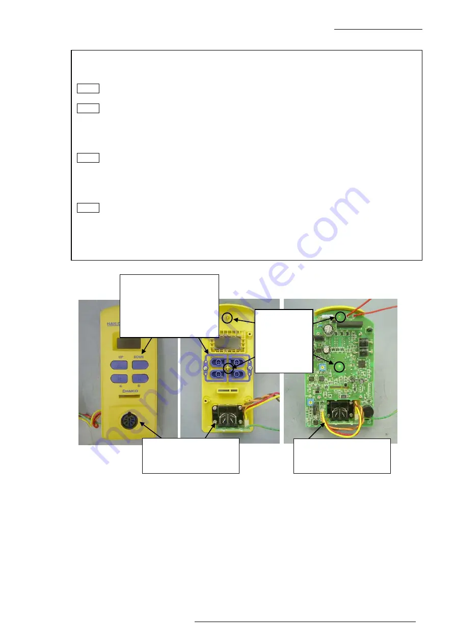
(1) Attach the buttons R and L onto the front panel with 2 screws (P tight round head screw
M2.6 x 6). (Figs. 4-2-3 to 4-2-5)
NOTE Attach the buttons R and L properly, so as to correlate with the indications on the
front panel.
NOTE To prevent buttons from being cracked, be careful not to tighten screws excessively.
(2) Mount the P.W.B. (for connector) onto the front panel with the holder and 4 screws (P tight
round head screw M2.6 x 8). (Figs. 4-2-3 to 4-2-5)
(3) Mount the P.W.B. (for control) onto the front panel with 4 screws (P tight round head
screw M2.6 x 8). (Figs. 4-2-2, 4-2-5 and 4-2-6)
NOTE Align the holes of the P.W.B. with 2 depressed sections of the front panel.
(4) Run the lead wire of the connector section under the P.W.B. to insert and pull the card
smoothly. (Fig. 4-2-6)
(5) Mount the grounding wire of the P.W.B. onto the grounding plate with 1 screw (round
head screw M4 x 6). (Fig. 4-2-1)
NOTE Run the grounding wire as close as possible to parallel with the edge of the grounding
plate and attach it together with the grounding wire for jack.
(6) Solder the lead wire of the P.W.B. to the secondary side of the transformer.
(7) Plug the connector for jack into the P.W.B. (4-2-1)
(8)
Close the case. (Refer to the assembly procedures in Section 4-1.)
Fig. 4-2-6
When attaching buttons:
• Correlate with the
indications on the front
panel
• Be careful not to tighten
screws excessively.
Run the lead wire under
the P.W.B. to insert and
pull the card smoothly.
Fig. 4-2-4
Fig. 4-2-5
Appearance where the
holder was installed and
secured with screws
Press-fit the
depressed
section of the
front panel
into the hole
of the P.W.B.


