First Edition: March 31, 2007
4-4 Jack (FX-951/FH-200)
●
Assembly procedures (Jack)
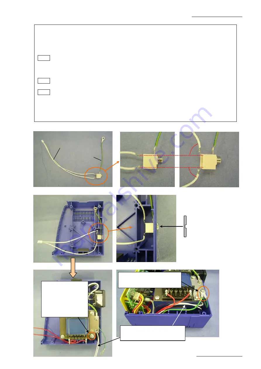
(1) Solder the grounding wire to the jack. (4-4-4)
(2) Solder the white lead wires leading from the P.W.B. to the jack and bend the terminal at 90º.
(4-4-4 to 4-4-6)
(3) Attach the jack to Case L. (4-4-7 to 4-4-8)
NOTE Note that the jack nut attachment orientation is specified. Be careful not to install it
backwards. (4-4-8)
(4) Attach the transformer and grounding plate to the case L with 4 screws (TP Binding B1
M3.5 x 45). (4-4-9)
NOTE Install the external tooth lock washer (M4) at the designated position of the
transformer.
NOTE Make sure that the lead wires for jack does not get caught.
(5) Attach the grounding wires for jack and P.W.B. to the grounding plate with one screw (pan
head screw M4 x 6). (4-4-10)
(6) Insert the connector for jack into the P.W.B. (4-4-1)
(7) Close the case. (Refer to the assembly procedures in Section 4-1.)
4-4-4
4-4-5
4-4-6
90
°
90
°
Grounding wire
Two white lead wires to be
connected to the P.W.B.
(They do not have polarities
.)
4-4-9
4-4-10
4-4-7
4-4-8
Attach the nut with
the non-groove side
facing toward the
case.
Install the external
tooth lock washer
between the
grounding plate and
transformer at the
marked position.
Attach the grounding wires
for P.W.B. and jack together.
Run the lead wires for jack as
shown in 4-4-9 and 4-4-10.


