First Edition: March 31, 2007
4-3 Power Receptacle, Power Switch and Transformer (FX-951/FH-200)
4-3
Power Receptacle, Power Switch and Transformer
(1) Follow the procedures in 4-1.
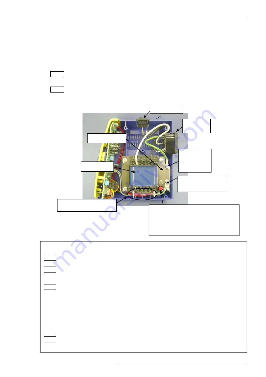
(2) Disconnect the grounding wire of the power receptacle from the grounding plate. (Photo
14)
(3) Desolder 3 soldered sections of the lead wire of the power receptacle.
(4) Desolder 2 soldered sections of the lead wire of the power switch.
(5) Desolder 2 soldered sections of the secondary lead wire of the transformer.
(6) Remove the grounding wire of the P.W.B. from the grounding plate.
NOTE
The grounding wire for P.W.B. is attached together with the grounding wire for jack.
(7) Remove 4 screws securing the transformer, grounding plate and chassis.
NOTE
The external tooth lock washer is installed in only one section. Be careful not to lose
it. (Photo 14)
Fig. 4-3-1
Case L
Secondary side of the
transformer
Transformer
Grounding
wire for
power
receptacle
Power switch
Power
receptacle
Grounding plate
Caution regarding external tooth lock
washer
The external tooth lock washer is installed
on this screw between the grounding plate
and transformer.
Grounding wires for
P.W.B. and jack
●
Assembly procedures (Power receptacle, power switch and transformer)
(1) Mount the transformer and grounding plate onto case L with 4 screws (TP Bind B1 M3.5 x 45).
NOTE
Install the external tooth lock washer (M4) in the designated place of the transformer.
(Fig. 4-3-1)
NOTE
Check that the cushion rubber A is installed in the case L. (Fig. 4-1-5)
(2) Mount the grounding wire of the P.W.B. onto the grounding plate with 1 screw (round head
screw M4 x 6). (Fig. 4-3-1)
NOTE Run the grounding wire as close as possible to parallel with the edge of the grounding
plate and attach it together with the grounding wire for jack
.
(3) Solder the lead wire of the P.W.B. to the secondary side of the transformer. (Fig. 4-3-1)
(4) Solder the black lead wire of the transformer and the black lead wire leading from the power
receptacle to the power switch. (Fig. 4-3-2)
(5) Solder the white lead wire of the transformer, the black lead wire leading from the power
switch and grounding wire to the power receptacle. (Fig. 4-3-3)
(6) Mount the grounding wire of the power receptacle to the grounding plate with 1 screw (round
head screw M4 x 6). (Fig. 4-3-1)
NOTE Mount the grounding wire to be aligned parallel with the grounding plate.
(7) Close the case. (Refer to Assembly Procedures in Section 4-1.)


