28
5. Installation (continued)
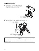
5.
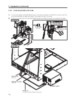
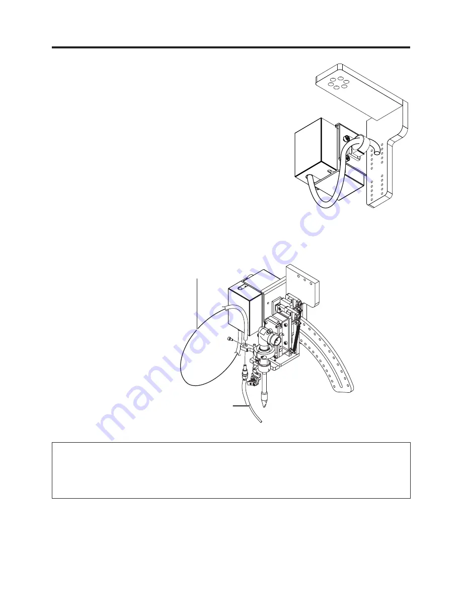
Open the cable clip on the upper part of the soldering
unit fixture base (CX5002), pass the tube unit through
the cable clip, and close the cable clip again.
— Note —
It is necessary to adjust the solder feed position of the solder feed guide and the Teflon tube
attachment method.
For adjustment method details, refer to “7-4-1 Solder Installation and Solder Feed Position
Adjustment” (p. 68).
6.
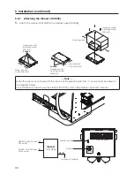
Attach tube unit B and the solder feed guide to the soldering unit mount.
Tube unit B (0.3 mm) (BX1054)
(0.5 – 1.0 mm) (BX1052)
(1.2 – 1.6 mm) (BX1053)
Tube unit B (0.3 mm) (BX1054)
(0.5 – 1.0 mm) (BX1052)
(1.2 – 1.6 mm) (BX1053)
Hexagon socket
head cap screw
M3×6
Solder feed guide (0.3 mm) (BX1046)
(0.5 – 1.0 mm) (BX1047)
(1.2 – 1.6 mm) (BX1048)

