33
5-3 External I/O Pin Layout
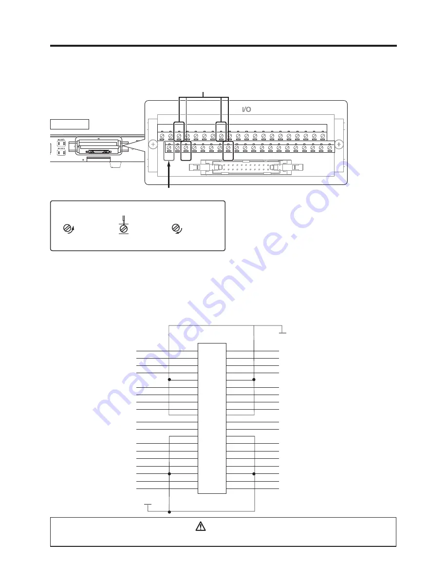
This is the I/O pin layout for input/output with external devices. It is used when assigning input signals
and output signals for use when running soldering programs or for external emergency stop circuits.
Connection is performed using the connector on the back of the robot. (The pins for OUT10 and
OUT11 are exclusively for connection to the cleaner.) Wiring should be performed using stranded wire
with a diameter of 0.5mm
2
(equivalent to AWG20).
CAUTION
To prevent electrical shock, be sure to ground the product during use.
XG4C-4031
CN6
N24 = 0 V
P24
IN0
IN2
IN4
IN6
1
3
5
7
9
11
13
15
17
27
29
31
33
35
37
39
19
21
23
25
2
4
6
8
10
12
14
16
18
28
30
32
34
36
38
40
20
22
24
26
OUT0
OUT2
OUT4
OUT6
OUT8
OUT10
OUT9
OUT11
OUT1
OUT3
OUT5
OUT7
IN8
IN10
IN12
IN14
IN16
IN18
IN17
IN19
IN9
IN11
IN13
IN15
IN1
IN3
IN5
IN7
5-3-1
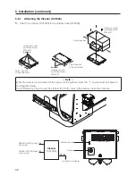
Wiring of the cleaner (CX1003)
The cleaner wires it like the diagram below.
1
3
5
7
9
11
13
15
17
19
21
23
25
27
29
31
33
35
37
39
2
4
6
8
10
12
14
16
18
20
22
24
26
28
30
32
34
36
38
40
Rear View
— Connecting of the lead —
Pull the lead, and confirm that it is not pulled out.
Loosen
the screw
Connect either to Vs of the cleaner (CX1003) side.
Connect to IN of the cleaner (CX1003) side.
Insert
the lead
Tighten
the screw


