8.6 Customizing the Toolbar
8-57
8
Useful Fu
nctions
8.6
Customizing the Toolbar
Overview
On the default toolbar, parts are randomly placed regardless of your preference or the frequency of
use.
The V-SFT editor supports the toolbar customizing function, thus, icons on the toolbar can be added,
changed, or deleted.
You can arrange the toolbar to suit your preference and enhance its usability.
Icon
How to Add
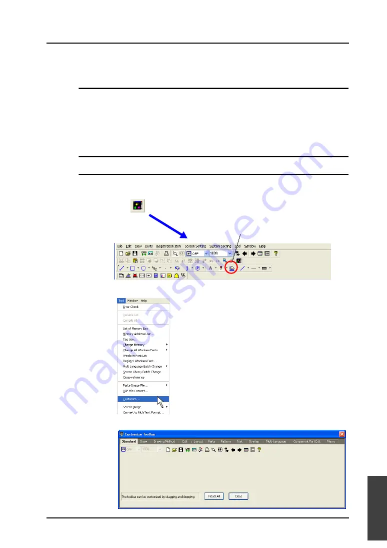
This section explains how to add the [Parts List] icon (= [Parts]
→
[Parts List]) to the extreme right of
the [Edit] toolbar as an example.
1.
Click [Customize] from the [Tool] menu.
2.
The [Customize Toolbar] dialog is displayed.
: Parts list
Newly added
Summary of Contents for V8 series
Page 1: ...V8series Operation Manual...
Page 2: ......
Page 4: ......
Page 12: ......
Page 16: ......
Page 30: ......
Page 45: ...1 3 Starting 1 15 1 Introduction 5 The selected screen data file is opened...
Page 50: ...1 4 Quitting 1 20 Please use this page freely...
Page 92: ...2 6 Screen Composition 2 42 Please use this page freely...
Page 263: ...4 4 Graphic Properties Setting 4 59 4 Drawing Example of Item Dialog Line Box Text...
Page 264: ...4 4 Graphic Properties Setting 4 60 Please use this page freely...
Page 348: ...5 18 Multi language 5 84 Please use this page freely...
Page 406: ...6 7 After Transfer Communication with PLC 6 58 Please use this page freely...
Page 413: ...7 1 Overview 7 7 7 Print Print Example Screen Output List Output...
Page 414: ...7 1 Overview 7 8 Table Print Screens Graphic library...
Page 415: ...7 1 Overview 7 9 7 Print System Setting Memory Use List...
Page 416: ...7 1 Overview 7 10 Use Cross reference Message For the graphic library...
Page 417: ...7 1 Overview 7 11 7 Print Animation...
Page 418: ...7 1 Overview 7 12 Please use this page freely...
Page 610: ...After Completion of Parts Editing A3 30 Please use this page freely...


