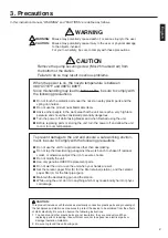

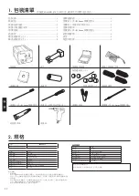
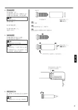

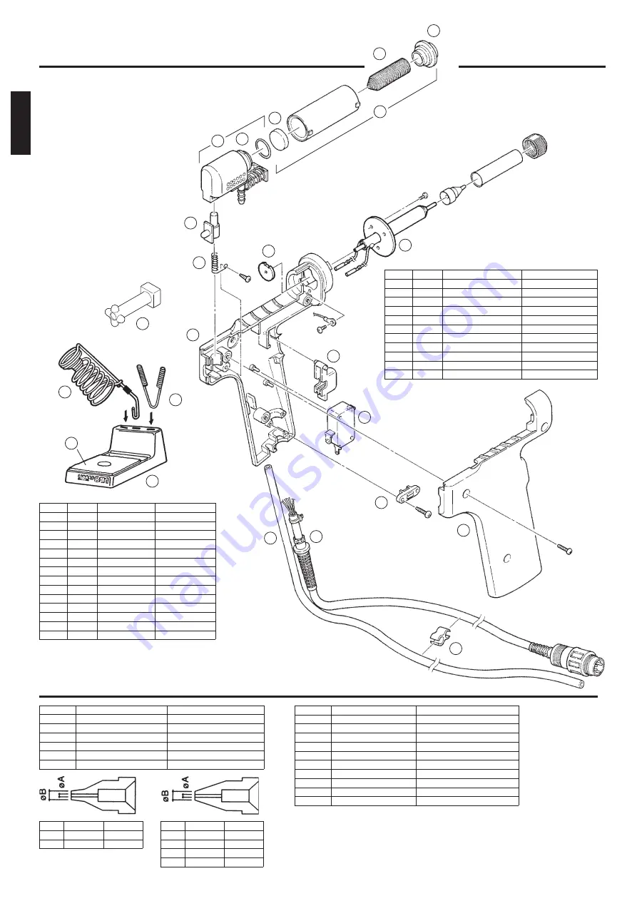
Specifications
For heating element
For ø0.8mm (0.03 in.) nozzle
For ø1.0mm (0.04 in.) nozzle
For ø1.3mm (0.05 in.) nozzle
For ø1.6mm (0.06 in.) nozzle
For ø0.8mm (0.03 in.) nozzle
For ø1.0mm (0.04 in.) nozzle
For ø1.3mm (0.05 in.) nozzle
For ø1.6mm (0.06 in.) nozzle
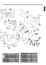
Specifications
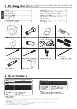
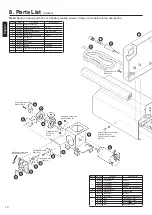
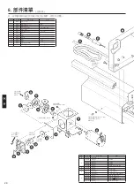
1
2
3
7
8
9
5
6
4
13
16
17
15
14
10
11
9
12
15
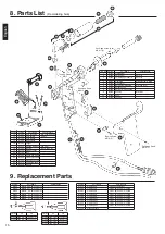
Item No.
1
2
3
4
5
6
7
8
9
10
11
Part No.
A1314
A1030
A1033
B2073
A1012
B1018
B1019
B1020
B2074
B1023
A1319
Part Name
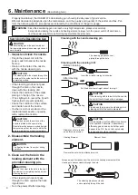
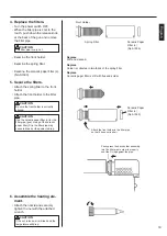
Front holder
Spring filter
Ceramic paper filter (L)
Filter pipe
O-ring (P12)
Back holder assembly
Release knob
Spring for release knob
Housing
Hose
Packing
Specifications
Set of 10
Set of 10
W/front holder & filters
W/O-ring (P12)
W/screws
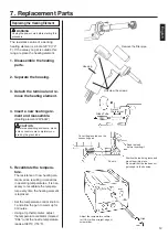
9. Replacement Parts
Part No.
A1002
A1003
A1004
A1005
A1006
A1007
Part Name
Nozzle S ø0.8mm (0.03 in.)
Nozzle S ø1.0mm (0.04 in.)
Nozzle ø0.8mm (0.03 in.)
Nozzle ø1.0mm (0.04 in.)
Nozzle ø1.3mm (0.05 in.)
Nozzle ø1.6mm (0.06 in.)
Part No.
A1002
A1003
øA
0.8mm (0.03 in.)
1.0mm (0.04 in.)
øB
1.8mm (0.07 in.)
2.0mm (0.08 in.)
Part No.
A1004
A1005
A1006
A1007
øA
0.8mm (0.03 in.)
1.0mm (0.04 in.)
1.3mm (0.05 in.)
1.6mm (0.06in.)
øB
2.3mm (0.09 in.)
2.5mm (0.1 in.)
3.0mm (0.12 in.)
3.0mm (0.12 in.)
Part No.
B1215
B1086
B1087
B1088
B1089
B1302
B1303
B1304
B1305
A1028
Part Name
Cleaning pin
Cleaning pin
Cleaning pin
Cleaning pin
Cleaning pin
Cleaning drill
Cleaning drill
Cleaning drill
Cleaning drill
Silicone grease
Pan Head Screw
M3
×
8 (3)
Tapping Screw
M3
×
8 (2)
Pan Head Screw
M2.6
×
3
Tapping Screw
M3
×
5
Pan Head Screw (Sus)
M2.6
×
7 (3)
Item No.
12
13
14
15
16
17
18
19
20
21
22
23
24
25
Part No.
B1025
B1024
B1022
B1026
B1021
A1313
A1003
B1723
B1724
B1094
B1095
A1042
B1470
B3048
Part Name
Cord assembly
Cord holder
Cord stopper
Micro switch
Trigger
Heating element
Nozzle
Element cover
Nut
Spring iron holder
Cleaning pin holder
Cleaning sponge
Iron holder base
Wrench
Specifications
W/micro switch & plug
Set of 4
24V, 50W
S ø1.0 (0.04 in.)
23
24
22
21
25
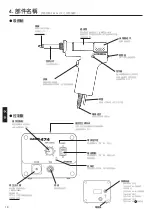
8. Parts List
English
(Desoldering Gun)
Summary of Contents for 474
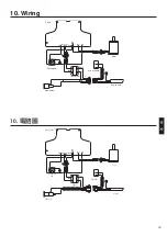
Page 19: ...3 18 1 2 M4 25 380 480 HAKKO...
Page 21: ...20 5 B1094 B1095 HAKKO 474 1 M4 25 2 3 4 IRON VACUUM...
Page 22: ...21 1 2 1 2 5 6 3 5 3 1 HAKKO 191 HAKKO 192 HAKKO 474 380 480 1 2 3 4 5 6...
Page 23: ...22 2 3 4 5...
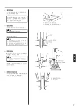
Page 24: ...23 1 HAKKO 475 HAKKO 475 HAKKO 475 2 1 3 3 2 1 A B A 70 80 25 25 5 25...
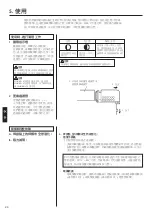
Page 25: ...24 HAKKO 474 B 25_26 20 25 26 24 20 28 a b c d e f...
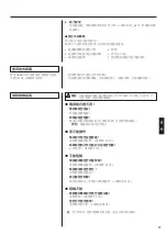
Page 26: ...6 25 HAKKO 474 1 2 3...
Page 27: ...26 6 A1033 A1033 4 A1033 5...
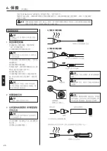
Page 28: ...27 1 A1009 2 1 2 3 A1009 S20 6 VACUUM...
Page 29: ...28 7 23 2 4 1 2 3 4 24V 50W 5 1 3 CAL 380 CAL...


