26
Operation
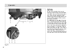
3.1.4
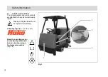
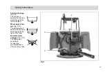
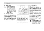
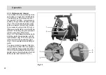
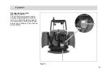
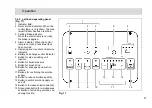
Solution tank
The solution tank is located behind the
driver's seat, on the right-hand side
(when facing the front). The solution
tank is a tank partitioned by a mem-
brane panel and has a volume of ap-
prox. 310 liters. Open up the gray tank
cap and secure it to fill the tank. Fill wa-
ter, max. 50 °C, and add the cleaning
agent in accordance with the manufac-
turer's instructions. Lower the cap again
to close it.
Only use cleaning agents (non-
foaming) suitable for the vehi-
cle's vendor.
We recommend using our clean and
care products which are specially bal-
anced for the scrubber drier. These
products meet the requirements stipu-
lated in the German Washing and
Cleansing Agent Act (WRMG). Observe
the correct dosage of the cleaning
agent. The correct dosage helps to re-
duce costs and protect the environ-
ment.
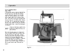
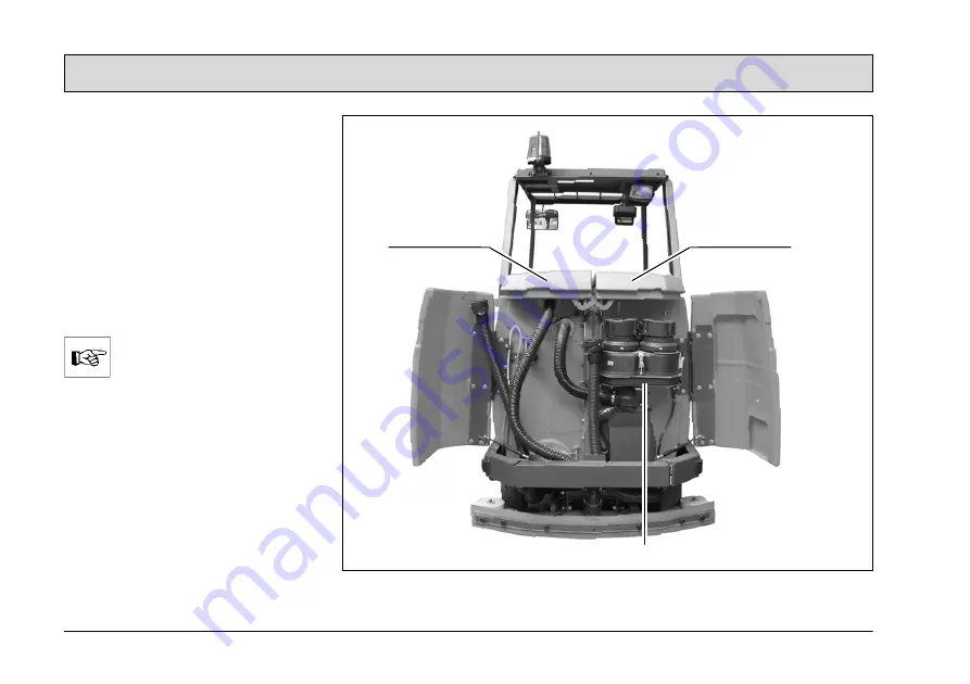
Fig. 12
3
1
2


