
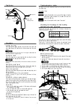
* Measure when the heating element is at room temperature.
Resistance value of heating
element (RED)
Resistance value of sensor
(BLUE)
2.5 – 3.5
43 – 58
Resistance value
of heating element
Resistance value
of sensor
If the resistance value is not normal, replace the heating
element.
(Refer to the instructions included with the replacement part.)
After replacing the heating element,
1. Measure the resistance value between pins 4 & 1 and 4 & 2, and
pins 5 & 1 and 5 & 2. If the resistance value is not infinite for all four
measurements, the heating element and sensor leads are
touching. This will damage the P.W.B. When reassembling, be
sure that the heating element and sensor leads do not touch.
2. Measure the resistance value ‘a’ ‘b’ ‘c’ to confirm that the leads are
not twisted and that the grounding spring is properly connected.
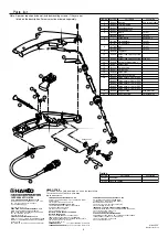
CAUTION
When reassembling, match the
convex part of the hexagon nut to
concave part of the housing.
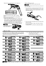
Broken soldering gun cord
There are two methods of testing the soldering gun cord.
CAUTION
The LED heater lamp will flicker even with a normal gun cord if the temperature
reaches 480
C (896
F).
1. Turn the unit on and set the temperature to 480
C (896
F). Then
wiggle and kink the gun cord at various locations along its length,
including strain relief area. If the LED heater lamp flickers, then the
cord needs to be replaced.
2. Check the resistance value between the pin of the plug and the
wire on the terminal.
Pin 1: Red Pin 2: Blue Pin 3: Green Pin 4: White Pin 5: Black
The value should be 0
.
If it is greater than 0
or is infinite, the cord should be replaced.
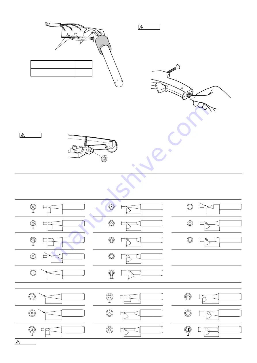
Parts list (Tips)
0
C
3
0.5(0.02)
900M-T-1.6D
0
C
5
0.5(0.02)
900M-T-2.4D
6.5
0.5(0.02)
900M-T-3.2D
0
C
951
900M-T-SB
0
C
900M-T-0.8C
-10
C/-18
F
900M-T-2C/900M-T-2CF*
0
C
900M-T-3C/900M-T-3CF*
0
C
900M-T-S4
0
C
900M-T-S10*
0
C
900M-T-S11*
0
C
951 tip out diam. ø6.5mm
• For heavy duty soldering Hakko recommends the 952 gun with heavier tips.
952
900L-T-B
0
C
900L-T-2B
0
C
0
C
900L-T-2.4D
900L-T-3.2D
0
C
-20
C/-36
F
900L-T-2C/900L-T-2CF*
0
C
900L-T-3C/900L-T-3CF*
900L-T-4C/900L-T-4CF*
0
C
900L-T-5C/900L-T-5CF*
0
C
900L-T-K
+20
C/+36
F
CAUTION
Use only genuine replacement tips for Hakko 951,952. The tips for Hakko Dash are not available to use.
These tips are tinned flat only.
952 tip out diam. ø8.5mm
(0.12)
ø
3.2
(0.09)
ø
2.4
(0.06)
ø
1.6
(0.25)
17(0.66)
17(0.66)
17(0.66)
(0.2)
(0.1)
14(0.55)
R0.2(0.008)
(0.08)
ø
2
900M-T-B/900M-T-BF2*
0
C
*BF2 is tinned a distance of 2mm (0.08 in.) from the end of the tip.
17(0.66)
R0.5(0.02)
17(0.66)
(0.031)
ø
0.8
45
17(0.66)
(0.08)
ø
2
45
17(0.66)
(0.1)
ø
3
45
900M-T-4C/900M-T-4CF*
0
C
17(0.66)
(0.16)
ø
4
45
15(0.6)
R0.25(0.01)
(0.08)
ø
2
17(0.66)
(0.1)
ø
3
55
17(0.66)
(0.16)
ø
4
55
20(0.79)
R0.5(0.02)
20(0.79)
R1(0.04)
20(0.79)
(0.09)
ø
2.4
5(0.2)
0.5(0.02)
20(0.79)
(0.12)
ø
3.2
8(0.32)
0.5(0.02)
20(0.79)
(0.08)
ø
2
45
20(0.79)
(0.1)
ø
3
45
20(0.79)
(0.16)
ø
4
45
15(0.6)
(0.2)
ø
5
45
18(0.71)
(0.2)
ø
5
2(0.08)
45
15(0.6)
900M-T-K
45
+30
C/+54
F
(0.2)
ø
5
2(0.08)
The tip temperature will vary according to the shape of the tip. The preferred
method of adjustment uses a tip thermometer. (Refer to the instruction manual
for the station.) A less accurate method involves adjusting the temperature
settings according to the adjustment value for each tips.
Examples: When using a 900M-T-0.8C tip at 400
C (750
F), the
difference between this tip and standard tip is –10
C (–18
F).
Set the temperature to 410
C (768
F).
Refer to the chart for the correct adjustment values.
3
Hexagon nut M4


