06-1491-00-12.fm
131
Attachments and Options
Checklist – Vacuum sweeping
Driving to the work site
1. Start the vehicle with the ignition switch
Fig. 113-78
2. As required, switch on the dipped headlight
Fig. 113-54
, working
spotlight
Fig. 113-55
Fig. 113-59
.
3. Prepare the transport mode. The brush arms must be swung in for the
transport mode. For this, use the joysticks
.
The sweeping unit must be in the upper end position. For this, use the
joystick
Fig. 114-70
4. Check the transport protection device, see page 130.
5. Drive to the work site. The transport mode information symbol
Fig. 113-A
appears in the multifunctional display.
6. Loosen the transport protection device, see page 130.
Switching vacuum sweeping on
Switch on the work mode with the Hako button
Fig. 114-72
. The accelera-
tor pedals must be in the neutral position. In the multifunctional display,
the information symbol for the vacuum sweeping system work
mode
Fig. 114-A
appears as 2-brush system or
Fig. 114-B
as 3-brush
system.
For a coded attachment, the Citymaster 1600 can automatically activate
the following functions through the Hako button:
•
The rotating brushes are lowered (floating position)
•
The rotating brush drives are switched on
•
The rotating brush speed is activated
•
The fresh water pump is switched on
•
The circulating water supply is switched on
•
The suction fan is switched on
The fresh water supply is interrupted and the rotating brush stopped if the
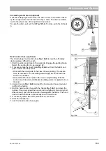
driver leaves the driver's seat! Restarting by pushing the left
joystick
Fig. 114-70
No.
Description
Reference
1
Driving to the work site
Page 131
2
Switching vacuum sweeping on
Page 131
3
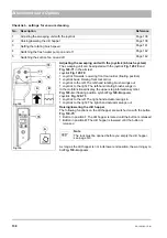
Setting the fixed engine speed
Page 132
4
Starting vacuum sweeping
Page 132
5
Sweeping dry surfaces
Page 132
6
Sweeping wet surfaces
Page 132
7
Sweeping larger objects
8
Changing the sweeping width
Page 133
9
Checking the overload protection
Page 134
Fig. 113:
1
2
P
0
A
Fig. 114:
A
B
Summary of Contents for Citymaster 1600
Page 22: ...22 01 1491 00 12 fm Safety Instructions G A B D E F Fig 3 C F C E C D G A B A...
Page 26: ...26 02 1491 00 11 fm Operation Fig 5 25 23 16 18 17 19 22 21 20 24 26 27...
Page 30: ...30 02 1491 00 11 fm Operation Fig 7 62 63 61 67 55 50 51 54 53 52 58 57 59 60 65 64 66 68 56...
Page 32: ...32 02 1491 00 11 fm Operation Fig 8 75 69 78 73 72 79 80 81 82 83 74 77 70 71 76 84...
Page 85: ...04 1491 00 11 fm 85 Technical Data 4 Technical Data Fig 80 3830 1600 941 1210 975 1964...
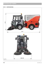
Page 146: ...146 06 1491 00 12 fm Attachments and Options 6 1 5 Technical data Fig 144 2215 4510 1580 2250...
Page 220: ...220 06 1491 00 12 fm Attachments and Options...


