144
06-1491-00-12.fm
Attachments and Options
Cleaning the suction mouth
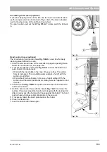
1. Lock the dirt hopper with the transport protection device, see page 130.
Drive the vehicle to a suitable cleaning place.
2. Select the working menu in the multifunctional display with the turn-
push knob. Switch the suction fan on in the suction fan menu item.
3. Push a water hose into the suction mouth
and loosen the
dirt with the water jet. The dirt is drawn with the water into the dirt hop-
per.
4. Empty the dirt hopper, see page 143.
In the case of heavy soiling, dismantle and clean the suction mouth, see
page 120.
Cleaning the dust filter and reducing piece
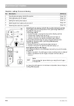
In the driver's cab under the driver's seat behind the cover plate
Fig. 139-49
are located the sieve filter
Fig. 139-A
and the reducing
piece
Fig. 139-B
of the water pump. Unscrew the filter housing, check the
sieve filter and the reducing piece for openness and clean if necessary.
Cleaning spray nozzles and ball valve filter
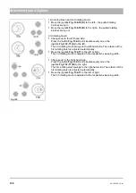
The spray nozzles
Fig. 140-A
for the rotating brushes are located on the
sweeping unit. A ball valve filter is located in the filter holder
Fig. 140-B
in
front of a distributor. Dismantle and clean the spray nozzles and ball valve
filter.
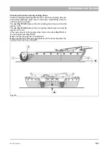
Cleaning the suction fan
1. Lock the dirt hopper with the transport protection device, see page 130.
Drive the vehicle to a suitable cleaning place.
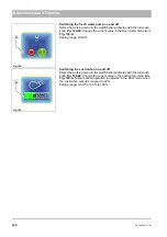
2. Connect a water hose to the water connection
Fig. 141-A
of the dirt
hopper.
3. Push the Hako button
and let the water be drawn as required
by the suction fan into the dirt hopper.
4. Open the lid of the dirt hopper and raise the dirt hopper up to the end
stop with the button
and drain off the water taken up!
Fig. 138:
87
B
Fig. 139:
A
A
B
Fig. 140:
Fig. 141:
A
Summary of Contents for Citymaster 1600
Page 22: ...22 01 1491 00 12 fm Safety Instructions G A B D E F Fig 3 C F C E C D G A B A...
Page 26: ...26 02 1491 00 11 fm Operation Fig 5 25 23 16 18 17 19 22 21 20 24 26 27...
Page 30: ...30 02 1491 00 11 fm Operation Fig 7 62 63 61 67 55 50 51 54 53 52 58 57 59 60 65 64 66 68 56...
Page 32: ...32 02 1491 00 11 fm Operation Fig 8 75 69 78 73 72 79 80 81 82 83 74 77 70 71 76 84...
Page 85: ...04 1491 00 11 fm 85 Technical Data 4 Technical Data Fig 80 3830 1600 941 1210 975 1964...
Page 146: ...146 06 1491 00 12 fm Attachments and Options 6 1 5 Technical data Fig 144 2215 4510 1580 2250...
Page 220: ...220 06 1491 00 12 fm Attachments and Options...


