162
06-1491-00-12.fm
Attachments and Options
6.2.4
Operation
Checklist – Before start-up of the mowing system
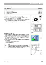
Checking the transport protection device
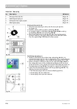
The transport protection device is located on the left side of the mower.
The mower is set for the relevant operation with the mounting bolt
. The following settings are possible:
•
Mowing: Take the mounting bolt out from the mounting position, see the
illustration (the mower must float freely).
•
Transport: The mounting bolt must secure the mower in the upper
position
Fig. 157-B
.
•
Cleaning: The mounting bolt must secure the mower in the lower
position
Fig. 157-C
.
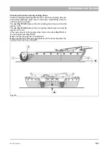
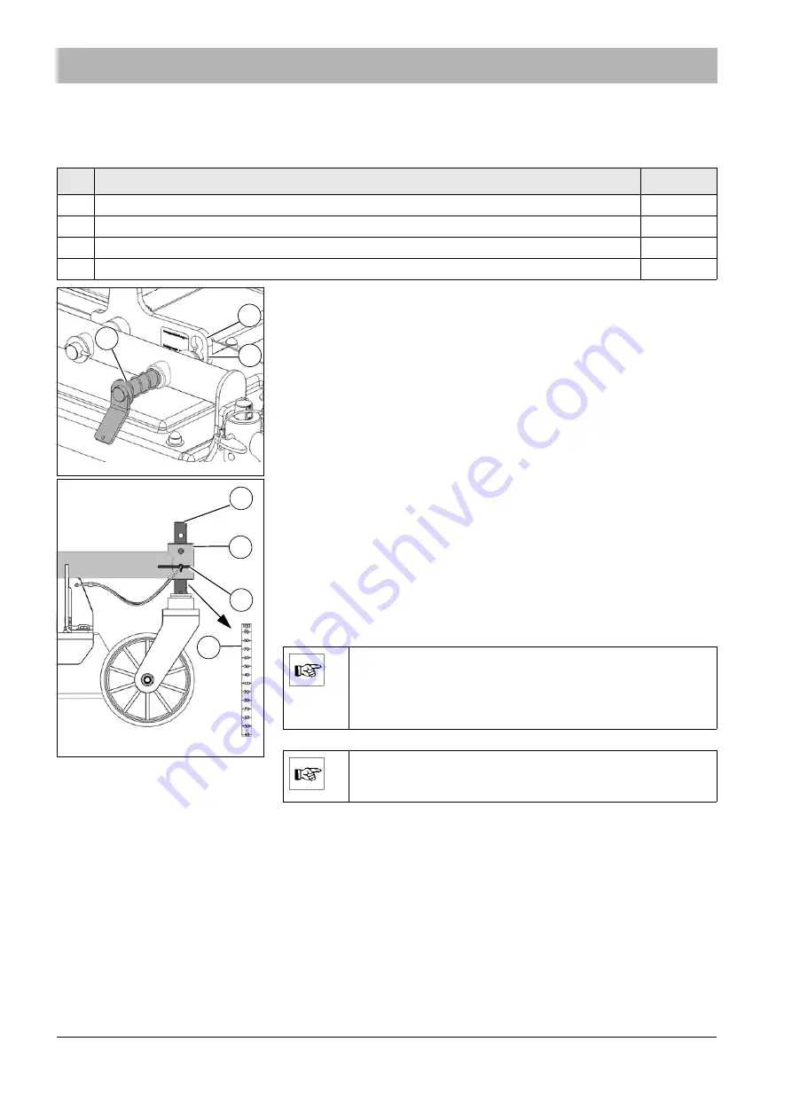
Adjusting the cutting height
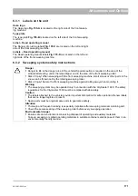
1. Place the vehicle on a level surface and hold it with the parking brake.
Raise the mower with the joystick
. Switch the engine off
and pull out the ignition key.
2. Pull the mounting bolt
Fig. 158-C
of
Fig. 158-B
of the wheel spar until the
wanted cutting height is set. You can adjust the cutting height centime-
tre by centimetre with the two mounting holes in the bush.
3. You can read off the cutting height on the scale
Fig. 158-D
.
4. Secure the set cutting height with the mounting bolt.
Preparing the dirt hopper
No.
Description
Reference
1
Checking transport protection device
Page 162
2
Adjusting the cutting height
Page 162
3
Preparing the dirt hopper
Page 162
4
Checking and if necessary changing the mowing blades and V-belt
Page 168
Fig. 157:
B
A
C
Fig. 158:
B
A
C
D
Note
The setting of the cutting height must be the same for all
wheels.
If the grass is very long and wet, you are recommended firstly
to cut high and then to cut low once again.
Note
Mowing without circulating water! Lock the sump valve, see
page 145.
Summary of Contents for Citymaster 1600
Page 22: ...22 01 1491 00 12 fm Safety Instructions G A B D E F Fig 3 C F C E C D G A B A...
Page 26: ...26 02 1491 00 11 fm Operation Fig 5 25 23 16 18 17 19 22 21 20 24 26 27...
Page 30: ...30 02 1491 00 11 fm Operation Fig 7 62 63 61 67 55 50 51 54 53 52 58 57 59 60 65 64 66 68 56...
Page 32: ...32 02 1491 00 11 fm Operation Fig 8 75 69 78 73 72 79 80 81 82 83 74 77 70 71 76 84...
Page 85: ...04 1491 00 11 fm 85 Technical Data 4 Technical Data Fig 80 3830 1600 941 1210 975 1964...
Page 146: ...146 06 1491 00 12 fm Attachments and Options 6 1 5 Technical data Fig 144 2215 4510 1580 2250...
Page 220: ...220 06 1491 00 12 fm Attachments and Options...


