06-1491-00-12.fm
213
Attachments and Options
Checking the brushes
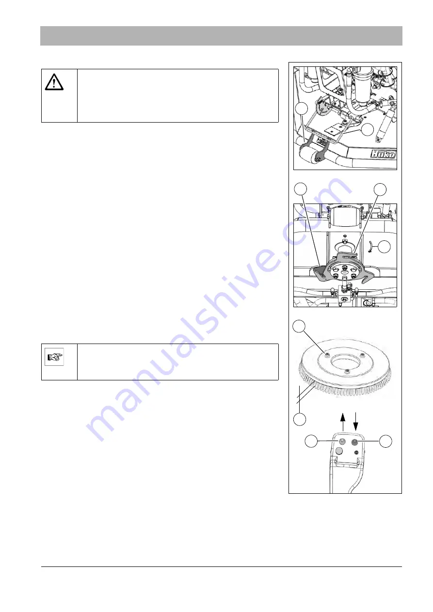
Check the brushes
of the scrubbing deck daily.
Replace worn brushes. The dimension
must be at least
10 mm. The brushes can be removed without tools.
Remove brushes by hand:
1. Raise the scrubbing deck with the joystick
.
2. Bring the locking bow
into the service position (wrench sym-
bol) and hook it onto the holder
.
3. Remove the worn brushes from the carrier plates
. To do
this, remove the brush from the catch up
by rotating it jerkily
in the motor's direction of rotation (see arrow
Fig. 219-G
at the hous-
ing).
4. Mount the new brushes one after the other to the carrier plates. For
this, align the carrier disks
of the brushes to the carrier
plate
Fig. 219-D
and let the brush engage at the catch up (click sound)
by rotating it against the motor's direction of rotation.
Automatic brush ejection:
1. Raise the scrubbing deck with the joystick
.
2. Pull the left joystick
back and press the right
joystick
forward at the same time. The brushes are ejected.
3. Remove the worn brushes from the scrubbing deck.
4. Mount the new brushes one after the other to the carrier plates. For
this, align the carrier disks
of the brush to the carrier
plate
Fig. 219-D
. Let the brush engage at the catch up (click sound) by
rotating it against the motor's direction of rotation.
Fig. 219:
E
D
B
F
C
G
X
Warning
•
Risk of injury! Always wear protective gloves when working
on the brushes.
•
Risk of injury! Please be particularly careful in the area of
the scrubbing deck when brushes are ejected automati-
cally.
Note
Only perform automatic brush ejection when the vehicle has
stopped. The driver must be on the driver's seat for ejecting
the brushes!
Summary of Contents for Citymaster 1600
Page 22: ...22 01 1491 00 12 fm Safety Instructions G A B D E F Fig 3 C F C E C D G A B A...
Page 26: ...26 02 1491 00 11 fm Operation Fig 5 25 23 16 18 17 19 22 21 20 24 26 27...
Page 30: ...30 02 1491 00 11 fm Operation Fig 7 62 63 61 67 55 50 51 54 53 52 58 57 59 60 65 64 66 68 56...
Page 32: ...32 02 1491 00 11 fm Operation Fig 8 75 69 78 73 72 79 80 81 82 83 74 77 70 71 76 84...
Page 85: ...04 1491 00 11 fm 85 Technical Data 4 Technical Data Fig 80 3830 1600 941 1210 975 1964...
Page 146: ...146 06 1491 00 12 fm Attachments and Options 6 1 5 Technical data Fig 144 2215 4510 1580 2250...
Page 220: ...220 06 1491 00 12 fm Attachments and Options...


