48
02-1491-00-11.fm
Operation
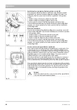
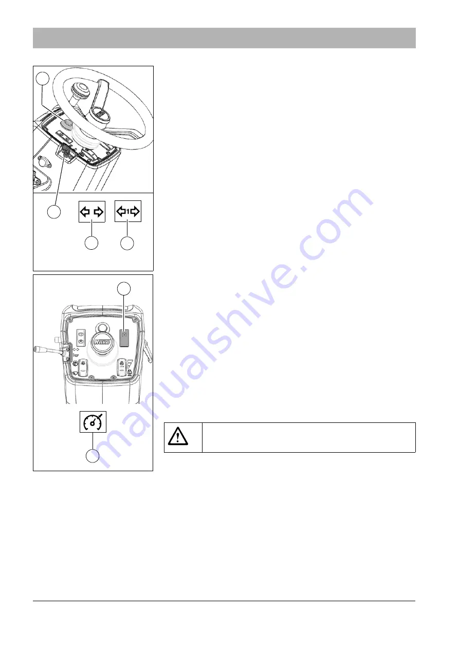
Switching the emergency flasher system on and off
The emergency flasher system is switched on and off with the switch
Fig. 31-61
. The direction indicators
and
Fig. 5-17
flash. The
emergency flasher system also functions in position P of the ignition
switch.
•
Switch in stage I: Emergency flasher system OFF
•
Switch in stage II: Emergency flasher system ON
The lamps are monitored. Fast flashing signals a defective lamp.
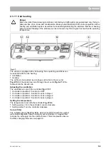
In the multifunctional display, the flasher information symbol
Fig. 31-A
appears, or in trailer operation the trailer operation flasher information
symbol
Fig. 31-B
.
Direction indicators
The direction indicators
Fig. 31-65
and
are switched on and off
. The direction indicators also function in position
P of the ignition switch.
•
Switch in stage I: Left direction indicator switch ON
•
Switch in stage II: Direction indicator switch OFF
•
Switch in stage III: Right direction indicator switch ON
The lamps are monitored. Fast flashing signals a defective lamp.
In the multifunctional display, the flasher information symbol
Fig. 31-A
appears, or in trailer operation the trailer operation flasher information
symbol
Fig. 31-B
.
Cruise control and speed limiter (optional)
The cruise control and speed limiter is available only in work mode. The
current speed is set in the first position of the switch
Fig. 32-68
. In this
case the road speed is controlled so that it is not lower or higher than the
speed set with the cruise control. The cruise control information symbol
Fig. 32-A
appears in the multifunctional display. The cruise control is
switched off again in the neutral position of the switch.
If the driver presses the accelerator pedal, the road speed is increased
without the cruise control being deactivated. For reasons of safety, the
cruise control switches off immediately when the brake pedal is operated.
The speed limiter determines the maximum road speed with the accelera-
tor pedal pushed down fully. This serves for convenient control of the road
speed especially at low working speeds. The speed must be set on the
configuration menu. It is activated via the second switch position of the
switch
Fig. 32-68
Fig. 31:
A
B
65
61
Fig. 32:
A
Danger
Risk of accident! Use the cruise control and the speed limiter
only when the traffic situation allows!
Summary of Contents for Citymaster 1600
Page 22: ...22 01 1491 00 12 fm Safety Instructions G A B D E F Fig 3 C F C E C D G A B A...
Page 26: ...26 02 1491 00 11 fm Operation Fig 5 25 23 16 18 17 19 22 21 20 24 26 27...
Page 30: ...30 02 1491 00 11 fm Operation Fig 7 62 63 61 67 55 50 51 54 53 52 58 57 59 60 65 64 66 68 56...
Page 32: ...32 02 1491 00 11 fm Operation Fig 8 75 69 78 73 72 79 80 81 82 83 74 77 70 71 76 84...
Page 85: ...04 1491 00 11 fm 85 Technical Data 4 Technical Data Fig 80 3830 1600 941 1210 975 1964...
Page 146: ...146 06 1491 00 12 fm Attachments and Options 6 1 5 Technical data Fig 144 2215 4510 1580 2250...
Page 220: ...220 06 1491 00 12 fm Attachments and Options...

