02-1491-00-11.fm
59
Operation
2.3.11 Cab heating
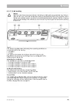
The vehicle is equipped with cab heating. Two operating conditions can
be selected with the cab heating:
•
Ventilation
•
Heating
The air flow is transported by a 3-stage suction fan to the air vents
Fig. 47-53
of the windscreen and through the air vents
Fig. 6-47
of the
foot well into the driver's cab.
Adjusting the ventilation
The ventilation is set with the controller
.
•
Controller in position 0: Suction fan OFF
•
Controller in position 1: Suction fan runs in stage 1
•
Controller in position 2: Suction fan runs in stage 2
•
Controller in position 3: Suction fan runs in stage 3
Setting the temperature
The temperature is set with the controller
Fig. 47-52
.
•
Setting warmer: Turn the controller
counter-clockwise
•
Setting colder: Turn the controller clockwise
Cab air filter
The installed cab air filter
Fig. 47-A
, which is located beneath the number
Fig. 4-15
, filters out largely dust and pollen. A clogged filter
reduces the air supply into the vehicle interior. Therefore please observe
the filter changing intervals, see page 90.
Danger
Risk of accident! Good viewing conditions contributing to traffic safety are guaranteed only if all win-
dows are free of ice, snow and condensation. Make yourself familiar with the correct operation of the
heating and ventilation system as well as de-moisturising/defrosting the windows. Maximum heating
power and fast thawing of the windows can be achieved only if the engine has reached its operating
temperature.
Fig. 47:
A
51
52
53
Summary of Contents for Citymaster 1600
Page 22: ...22 01 1491 00 12 fm Safety Instructions G A B D E F Fig 3 C F C E C D G A B A...
Page 26: ...26 02 1491 00 11 fm Operation Fig 5 25 23 16 18 17 19 22 21 20 24 26 27...
Page 30: ...30 02 1491 00 11 fm Operation Fig 7 62 63 61 67 55 50 51 54 53 52 58 57 59 60 65 64 66 68 56...
Page 32: ...32 02 1491 00 11 fm Operation Fig 8 75 69 78 73 72 79 80 81 82 83 74 77 70 71 76 84...
Page 85: ...04 1491 00 11 fm 85 Technical Data 4 Technical Data Fig 80 3830 1600 941 1210 975 1964...
Page 146: ...146 06 1491 00 12 fm Attachments and Options 6 1 5 Technical data Fig 144 2215 4510 1580 2250...
Page 220: ...220 06 1491 00 12 fm Attachments and Options...


