
02-1481-00-00.fm
59
Operation
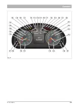
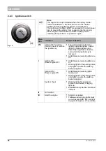
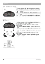
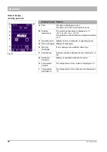
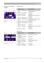
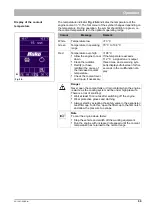
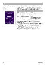
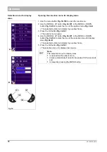
Display section –
operating data
Various operating parameters can be displayed in the operating data dis-
play section
. For changing the displayed operating parameter,
press the SCROLL UP button
or the SCROLL DOWN
button
.
C
Fig. 22:
Display section
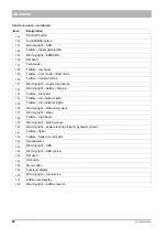
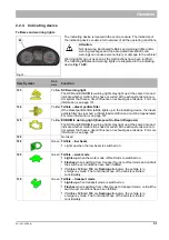
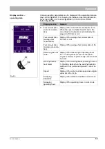
Remark
C
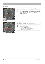
Fuel consumption
(current consump-
tion)
Display of the current fuel consumption in l/h
When the speed is higher than 10 km/h, the
current fuel consumption is automatically dis-
played in l/100 km or mi/l.
Fuel consumption
(
average fuel
consumption)
Display of the average fuel consumption in
l/100 km or mi/l.
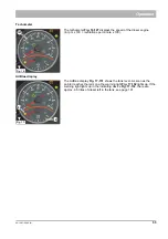
Fuel consumption
(average consump-
tion)
Display of the average fuel consumption in l/h.
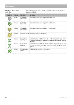
Diesel engine hour
meter
Display of the diesel engine operating hours
in h. Counting starts as soon as the diesel
engine is started. Is permanently saved, cannot
be reset.
Work hydraulics
hour meter
Display of the work hydraulic operating hours in
h. Counting starts when the work hydraulics is
switched on. Is permanently saved, cannot be
reset.
Speed
Display of the current vehicle speed as a digital
value in km/h or mph.
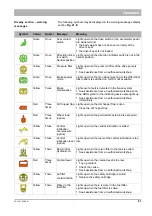
Sweeping
kilometres
Display of the distance travelled in work mode
Sweeping
operating hours
Display of the operating hours in work mode
Summary of Contents for Citymaster 2200
Page 35: ...02 1481 00 00 fm 35 Operation Fig 3 34 31 29 32 33 34 35 36 37 30...
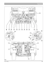
Page 39: ...02 1481 00 00 fm 39 Operation Fig 5 73 74 71 72 72 71 74 75 76 82 83 84 77 78 79 81...
Page 43: ...02 1481 00 00 fm 43 Operation Fig 7 114 116 117 118 119 120 115 113 112...
Page 236: ...236 05 1481 00 00 fm Maintenance and servicing...


