76
02-147015-00-00.fm
Use
2.4.4
Connections for front attachments
The following devices can be operated with the connections for the front
attachments
•
A
= Supply for hydraulic cylinder for side adjustment
•
B
= Return for hydraulic cylinder for side adjustment
•
C
= Water connection for sweeping unit spray nozzles
•
D
= Return 25/29/35 l/min (hydraulic circuit I)
•
E
= Supply 25/29/35 l/min (hydraulic circuit I)
•
F
= Return leakage oil pipe (e.g. for mower)
•
G
= Ball cock for locking suction mouth lift (e.g. mower)
•
H
= X63 socket 19-pin for attachments
Switching on the hydraulic circuit
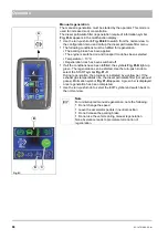
Select the A menu in the multifunction display with the turn-push knob
. Change the current value in the hydraulic circuit I menu item
Fig. 70-X
. Setting range: ON/OFF. Required for attachments without cod-
ing plug! The hydraulic circuit is switched off if the driver leaves the
driver's seat.
Fig. 69:
Note
The hydraulic couplings are marked with coloured rings and
engraving, see example
.
Fig. 70:
A
B
C
D
E
F
G
H
X
Summary of Contents for Citymaster 650
Page 23: ...01 147015 00 00 fm 23 Safety Instructions G A B D E F Fig 3 C F E C D G A A B H H C...
Page 27: ...02 147015 00 00 fm 27 Use Fig 5 24 19 25 23 22 21 20 16 18 17 10 26...
Page 31: ...02 147015 00 00 fm 31 Use Fig 7 63 64 66 65 62 68 67 56 51 52 55 54 53 59 58 60 61 57...
Page 33: ...02 147015 00 00 fm 33 Use Fig 8 74 69 76 70 72 71 77 78 79 80 81 73 75 82...
Page 97: ...04 147015 00 00 fm 97 Technical data 4 Technical data Fig 96 1270 982 3326 2269 866 1074 1200...


