23
Operation
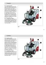
3.1.2 Solution system
The solution system is comprised of a
tank, pump, valve and spray jets. The
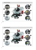
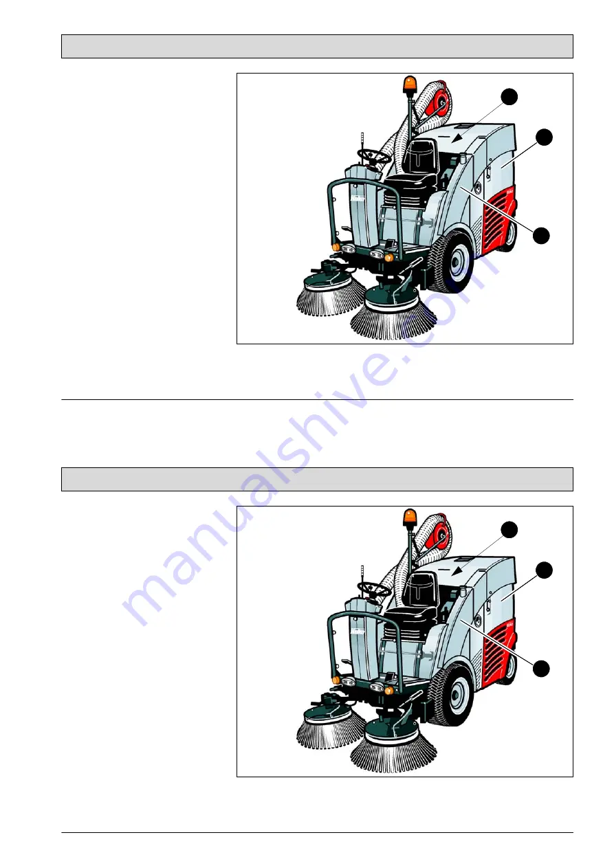
solution tank (Fig. 6/1) is located to the
left of the driver's seat and has a
volume of 100 liters. An electrical pump
feeds the solution to the spray jets. The
spray jets are arranged at the front on
the circular brush frame so that the jet
for solution sprays in front of the
brushes binding the dust and wetting
the surface prior to being cleaned by
the brushes. There is another spray jet
located in front of the fan. If the metal
filter option is installed, there is a spray
jet on the vacuum nozzle.
3.1.3 Sweepings container
The waste is vacuumed up by means of
the suction turbine (Fig. 6/2) and forced
into the sweepings container (Fig. 6/3).
To bind the dust optimally, solution from
the solution system is also supplied to
the vacuum nozzle.
Fig.6
2
1
3

