29
Operation
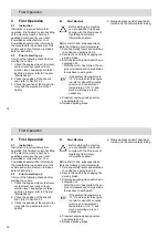
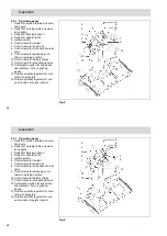
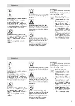
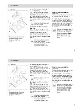
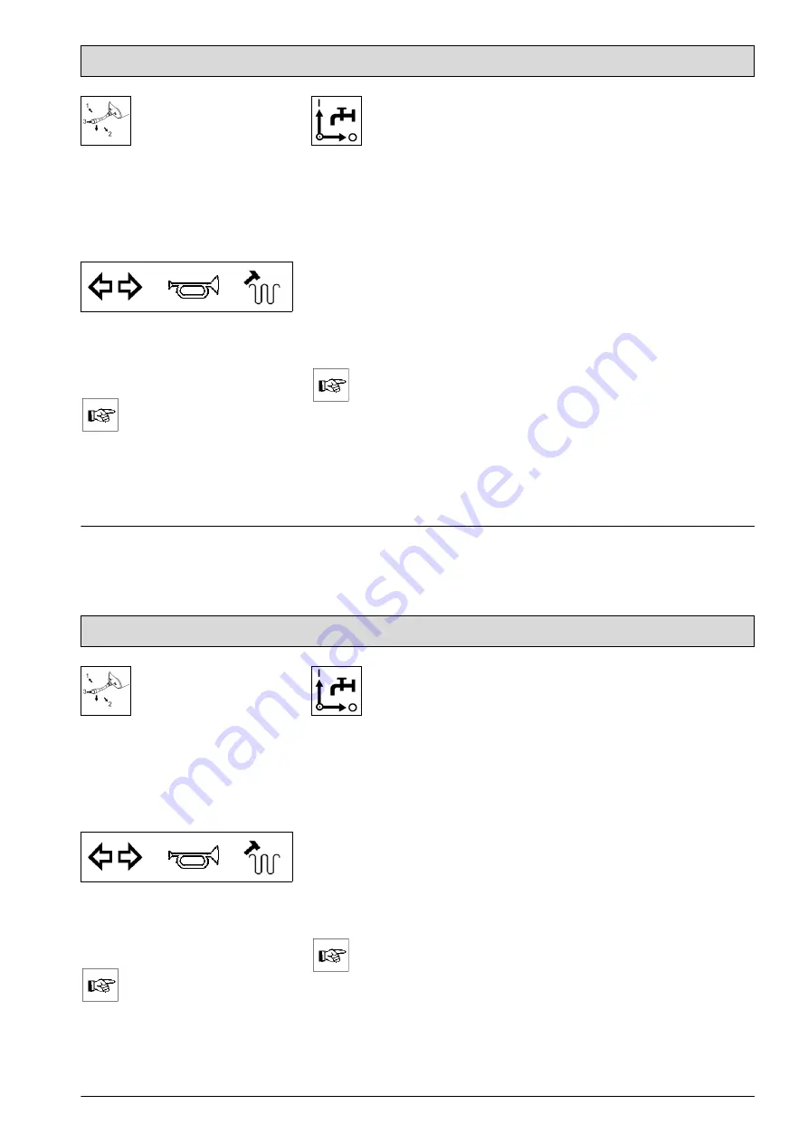
Combination switch (Fig. 9/12)
It controls the following functions:
• Switch direction 1 = indicator right
• Switch direction 2 = indicator left
• Switch direction 3 = horn
• Switch direction down = agitating
motor
The agitating motor switches off
automatically after approx. 20 sec.
Repeat the agitation process, if
necessary.
The suction turbine must be
switched off.
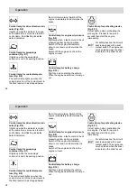
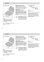
Solution quantity regulator for
circular brushes (Fig. 9/13)
This lever opens and closes the
solution supply for the circular brush
spray jets.
Position I = open
Position o = closed
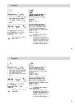
Solution quantity regulator for
suction nozzle jets (Fig. 9/14)
Only with the metal filter option!
This lever opens and closes the
solution supply for the vacuum nozzle.
Position I = open
Position o = closed
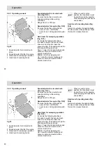
Condition: solution pump is
switched on.
The quantity of the solution
must be set so that the dust in
the area being swept is bound
properly. In the case of damp
working conditions, do not use
the solution quantity regulator.

