
47
Maintenance and Care
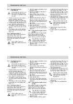
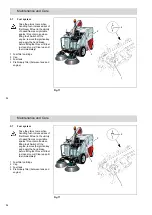
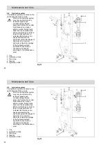
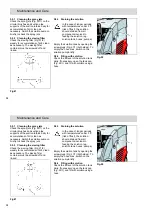
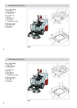
5.4.1 Opening the engine
compartment
Always allow the engine to cool
down before starting work in
the engine compartment. Risk
of burns!
1. Park the vehicle on a level surface
with the engine at operating
temperature. Raise the sweepings
container using the lever (Fig. 14/5).
2. Turn the engine off and allow to cool
down. Apply the parking brake.
3. If necessary, unlock the side panel
(Fig. 14/2) with a square wrench and
open it.
4. If necessary, unscrew the retaining
screws and remove the side panel
(Fig. 14/1).
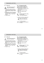
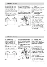
5.4.2 Refilling engine oil
Check the engine oil level with the oil
dipstick (Fig. 14/4) every day.
Refill engine oil as necessary or when
the engine oil pressure control lamp
lights up.
Only use the engine oil
prescribed, refer to Technical
Data!
1. Open the engine compartment, see
paragraph 5.4.1.
2. Pull the oil dipstick out and wipe it
with a clean cloth.
3. Compare the oil level with the
marking at the bottom end of the oil
dipstick.
4. Open the cap (Fig. 14/3). Do not
pour in too much oil at one time.
Allow the oil a few minutes to run into
the oil sump. Then measure the oil
level again.
5. Replace the cap and oil dipstick.
6. Close the side door.
7. The engine control lamp should go
out a few seconds after switching the
engine on.
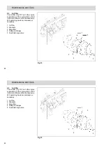
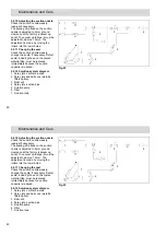
5.4.3 Changing the engine oil and
oil filter
The engine oil must be changed after
the first 50 operating hours and
subsequently every 250 operating
hours, once a year at the very least.
Pay attention to hot engine
parts and when draining hot
engine oil. Risk of burns!
1. Open the engine compartment, see
paragraph 5.4.1.
2. Place a suitable collecting vessel
under the drain plug of the oil sump.
Oil quantity with oil filter: 1.6 liter
Oil quantity without oil filter: 1.4 liter
3. Remove the drain plug from the oil
sump and drain the engine oil into
the collecting vessel.
4. Disassemble the oil filter (Fig. 14/5)
and install a new oil filter with a new
sealing ring (tighten hand-tight).
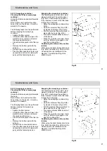
Dispose of the waste oil and
used oil filter according to the
applicable environmental
regulations!
5. Insert the drain plug with a new
sealing ring.
6. Fill the engine oil, see paragraph
5.4.2.
47
Maintenance and Care
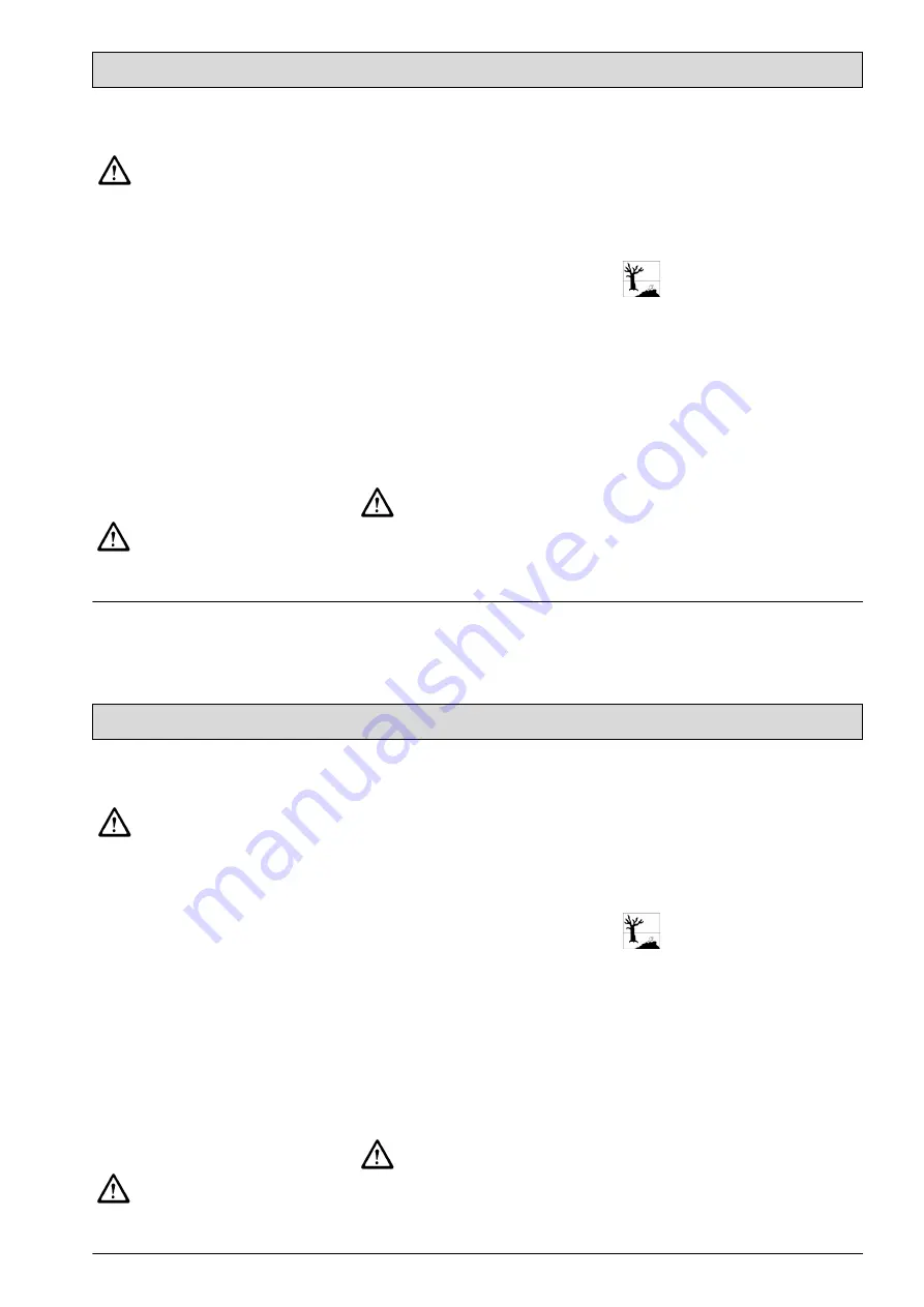
5.4.1 Opening the engine
compartment
Always allow the engine to cool
down before starting work in
the engine compartment. Risk
of burns!
1. Park the vehicle on a level surface
with the engine at operating
temperature. Raise the sweepings
container using the lever (Fig. 14/5).
2. Turn the engine off and allow to cool
down. Apply the parking brake.
3. If necessary, unlock the side panel
(Fig. 14/2) with a square wrench and
open it.
4. If necessary, unscrew the retaining
screws and remove the side panel
(Fig. 14/1).
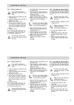
5.4.2 Refilling engine oil
Check the engine oil level with the oil
dipstick (Fig. 14/4) every day.
Refill engine oil as necessary or when
the engine oil pressure control lamp
lights up.
Only use the engine oil
prescribed, refer to Technical
Data!
1. Open the engine compartment, see
paragraph 5.4.1.
2. Pull the oil dipstick out and wipe it
with a clean cloth.
3. Compare the oil level with the
marking at the bottom end of the oil
dipstick.
4. Open the cap (Fig. 14/3). Do not
pour in too much oil at one time.
Allow the oil a few minutes to run into
the oil sump. Then measure the oil
level again.
5. Replace the cap and oil dipstick.
6. Close the side door.
7. The engine control lamp should go
out a few seconds after switching the
engine on.
5.4.3 Changing the engine oil and
oil filter
The engine oil must be changed after
the first 50 operating hours and
subsequently every 250 operating
hours, once a year at the very least.
Pay attention to hot engine
parts and when draining hot
engine oil. Risk of burns!
1. Open the engine compartment, see
paragraph 5.4.1.
2. Place a suitable collecting vessel
under the drain plug of the oil sump.
Oil quantity with oil filter: 1.6 liter
Oil quantity without oil filter: 1.4 liter
3. Remove the drain plug from the oil
sump and drain the engine oil into
the collecting vessel.
4. Disassemble the oil filter (Fig. 14/5)
and install a new oil filter with a new
sealing ring (tighten hand-tight).
Dispose of the waste oil and
used oil filter according to the
applicable environmental
regulations!
5. Insert the drain plug with a new
sealing ring.
6. Fill the engine oil, see paragraph
5.4.2.


