
2. Broken cord assembly
7. MAINTENANCE
Tip temperature
Cleaning
When not in use
After use
8. CHECK PROCEDURE
WARNING
1. Broken heating element / sensor
Rub lightly with sand-paper or
steel wool.
Be sure to measure the resistance of the heating element in both handles A and B.
If one of the heating elements is broken, replace both heating elements.
Heating element (Red)
Sensor (Blue)
8. CHECK PROCEDURE
9. PARTS LIST
●
HAKKO FX-8804 Hot Tweezer
9. PARTS LIST
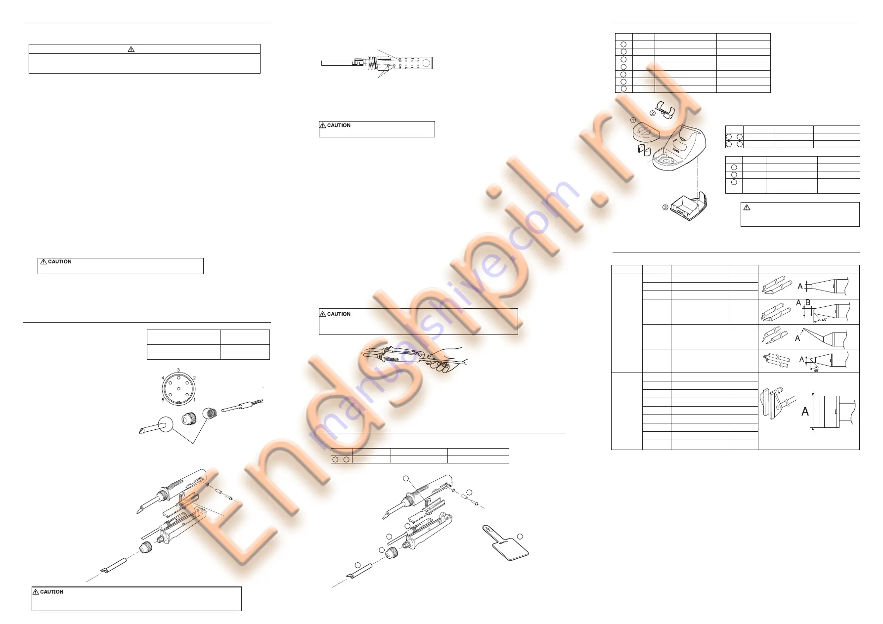
10. TIP STYLES
●
HAKKO FX-8804
A1577
A1379
A1378
A1388
A1389
A1576
A1390
A1391
A1380
A1381
A1382
A1392
A1383
A1384
A1385
Tip /CHIP 0.5L
Tip /CHIP 1L
Tip /CHIP 2L
Tip /CHIP 0.5C
Tip /CHIP 0.5I
Tip /CHIP 2.6C
Tip /SOP 4L
Tip /SOP 6L
Tip /SOP 8L
Tip /SOP 10L
Tip /SOP 13L
Tip /SOP 15L
Tip /SOP 18L
Tip /SOP 20L
Tip /SOP 25L
0.5 mm
1 mm
2 mm
1.5(0.5)
R0.25
2.6
4 mm
6 mm
8 mm
10 mm
13 mm
15 mm
18 mm
20 mm
25 mm
For
CHIP
For
SOP
Shape
Size A(B)
Performing proper and periodic maintenance extends product life and contributes to the
quality of soldering work. Efficient soldering depends upon the temperature, the quality and quantity of
the solder and flux. Apply the following service procedure as dictated by the conditions of the usage.
Since the tip can reach a very high temperature, please work carefully.
Except where indicated, always turn the power switch OFF and disconnect the power plug
before performing any maintenance procedure.
High temperatures shorten tip life and may cause thermal shock to components.
Always use the lowest possible temperature. The excellent thermal recovery characteristics
of the HAKKO FX-888D ensures effective soldering at low temperature.
Always clean the tip before use to remove any residual solder or flux adhering to it.
Use a cleaning sponge or the HAKKO 599B tip cleaner.
Contaminants on the tip may have negative effects, including reduced heat conductivity,
which contribute to poor performance.
Never allow the unit to idle at a high temperature for extended periods. This will allow the
tip to become oxidized. Turn the power switch OFF. If it is to be out of service for
several hours, it is advisable to disconnect the power plug as well.
Always clean the tip and coat it with fresh solder after use. This guards against oxidation.
1. Set the temperature to 250℃(482℉).
2. When the temperature stabilizes, clean the tip and
check the condition of the tip. If the tip is badly worn or deformed, replace it.
3. If the solder plated part of the tip is covered with black oxide, apply fresh solder,
containing flux, and clean the tip again. Repeat until all the oxide is removed,
then coat the tip with fresh solder.
4. Turn the power OFF and remove the tip, using the heat resistant pad. Set the tip aside to
cool.
Do not file the tip in an attempt to remove the black oxide.
Disconnect the plug of the cord assembly
and measure the resistance value
between the pin of the connecting plug as follows.
If the values of “a” and ”b” are outside
the value in the table, replace the heating
element(sensor) and/or cord assembly.
If the value of “c” is over the value in the
table, remove the oxidization film by lightly
rubbing with sand-paper or steel wool
the points shown in the drawing on the right.
●
●
Tip
Nipple
Handle A
Handle B
a. Between pins 4 & 5
(heating element)
b. Between pins 1 & 2 (Sensor)
c. Between pin 3 & tip
2.5 ~ 4.5 Ω
(at time of room temperature)
43 ~ 58 Ω
2 or less Ω
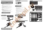
1. Loosen the nipple by turning it counterclockwise.
2. Pull out the tip.
3. Remove the screw and strut pin. Separate into handle A and B.
Remove the tension spring.
Do not lose the tension spring.
4. Remove each tapping screw of the handle A and B, and remove the handle cover.
5. Pull out the P.W.B. and heating element.
*Measure when the heating element is at room temperature.
1. Heating element resistance (red) 2.5-4.5 Ω
2. Sensor resistance (blue) 43-58 Ω
If the resistance value is not normal, replace the heating element.
(Refer to the instructions included with the replacement part.)
After replacement
1. Measure the resistance between pins 4 and 1, 4 and 2, 5 and 1, 5 and 2.
If it is not ∞, the heating element and sensor are touching. This will damage the circuit board.
2. Measure the resistance “a” , “b” and “c” to confirm that the leads are not twisted and that
the grounding spring is properly connected.
There are two methods of testing the cord assembly as below.
1. Turn the power on and set the temperature control knob to 400℃(752℉). Then, bend the cord
at various locations along its length, including in the strain relief area.
If the LED heater lamp flashes, then the cord needs to be replaced.
2. Check the resistance between the plug pin and the terminal lead.
Pin 1: Red Pin 2: Blue Pin 3 : Green
Pin 4 : White Pin 5 : Black
If it is higher than 0 Ω or ∞, the cord should be replaced.
The power lamp starts to flash when the temperature reaches 400℃(752℉)
regardless of the condition of the cord.
FX8804-02
HAKKO FX-8804
1
〜
6
AC26V 65W
Item No.
Part No.
Part Name
Specifications
Item No.
Part Name
Tip
Heating element
Nipple
Terminal
Tension spring
Strut pin
Heat resistant pad
A1578
B2289
B2290
B2295
B2296
B2300
1
2
3
4
5
6
7
Item No. Part No.
Part Name
Specifications
See”TIP STYLES”
2 PCS.
1
2
5
4
3
7
66
Nut
Strut pin
Screw
Tension spring
●
Tip Maintenance
●
Iron holder parts
●
HAKKO FH-800 Iron holder
Item No.
1
2
3
Item No.
1
〜
3
1
〜
3
Part No.
FH800-04BY
FH800-04SV
Part Name
HAKKO FH-800
HAKKO FH-800
Specifications
Blue-Yellow
Silver
Part No.
A1559
B3666
B3475
Part Name
Cleaning sponge
Holder clip
Bottom plate with
protection plate
Specifications
with Protective Sheet
& rubber foot
CAUTION
For safety reasons, please attach the protective sheet
to the bottom plate when using the HAKKO FX-8804.


