18
Operation
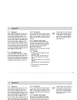
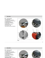
Accelerator lever (Fig. 5/1)
With the machine being switched on,
the accelerator lever allows continuous
regulation of speed. If pulled to maxi-
mum position, maximum speed is attai-
ned. Reduce speed by taking the lever
slowly back. If released, the lever auto-
matically returns into neutral position
and the machine stops (deadman
function). The parking brake of the tra-
vel drive is activated. The symbol of the
parking brake appears in the display.
Protect the machine against
rolling off before leaving it un-
attended. Before switching the
machine on again, make sure
that the accelerator lever is in
neutral position.
Opening of clear water tank (Fig. 5/2)
The clear water tank is filled after fol-
ding up the opening.
Hand lever for squeegee lift-out (Fig.
5/3)
Use this hand lever to lift and lower the
squeegee.
Clear water filter (Fig. 5/4)
While clear water flows from tank to
brush head, it is cleaned by the filter
element.
Soiled water drain hose (Fig. 5/5)
This hose allows draining the collected
soiled water from the tank.
Clear water drain hose (Fig. 5/6)
This hose allows draining the clear wa-
ter tank.
Brush ejector (Fig. 5/7)
The brush ejector makes brush removal
fast and easy.
Socket for charger unit (Fig. 5/8)
The socket serves to connect the speci-
al quick-charger approved by Hako.
Pedal brush head (Fig. 5/9)
Use this pedal to lift and lower the brush
head.
Pedal plate brush head pressure
(Fig. 5/10)
This pedal allows increasing the ground
pressure of the plate brush head.
Summary of Contents for Hakomatic B70 CL
Page 1: ...Instruction Manual Hakomatic B 70 CL 7061 37...
Page 41: ......


