


35
Maintenance and Service
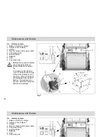
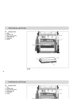
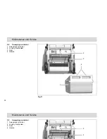
5.8.1 Emptying the sweepings con-
tainer
Check the fill level of the sweepings
container (Fig. 10/1) at regular intervals
(max. load capacity 25 kg) and empty
as necessary.
1. Switch the machine off and pull the
locking mechanism (Fig. 10/2) on the
sweepings container (Fig. 10/1) up-
wards.
2. Pull the sweepings container to the
rear out of the machine using the
handle (Fig. 10/4) and dispose of the
waste according to the applicable
environmental laws.
3. Reinstall the sweepings container
and press it against the locking
mechanism until it audibly latches
into place.
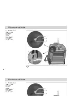
5.8.2 Changing the seal
Check the seal (Fig. 10/3) weekly for
signs of wear and change it as neces-
sary.
1. Switch off the machine and pull the
locking mechanism (Fig. 10/2) on the
sweepings container (Fig. 10/1) up-
wards.
2. Pull the sweepings container (Fig.
10/3) to the rear and out of the ma-
chine using the handle (Fig. 10/4).
3. Pull the seal on the sweepings con-
tainer from the filter support frame.
Install a new seal.
4. Reinstall the sweepings container
and press it against the locking
mechanism until it audibly latches
into place.
35
Maintenance and Service
5.8.1 Emptying the sweepings con-
tainer
Check the fill level of the sweepings
container (Fig. 10/1) at regular intervals
(max. load capacity 25 kg) and empty
as necessary.
1. Switch the machine off and pull the
locking mechanism (Fig. 10/2) on the
sweepings container (Fig. 10/1) up-
wards.
2. Pull the sweepings container to the
rear out of the machine using the
handle (Fig. 10/4) and dispose of the
waste according to the applicable
environmental laws.
3. Reinstall the sweepings container
and press it against the locking
mechanism until it audibly latches
into place.
5.8.2 Changing the seal
Check the seal (Fig. 10/3) weekly for
signs of wear and change it as neces-
sary.
1. Switch off the machine and pull the
locking mechanism (Fig. 10/2) on the
sweepings container (Fig. 10/1) up-
wards.
2. Pull the sweepings container (Fig.
10/3) to the rear and out of the ma-
chine using the handle (Fig. 10/4).
3. Pull the seal on the sweepings con-
tainer from the filter support frame.
Install a new seal.
4. Reinstall the sweepings container
and press it against the locking
mechanism until it audibly latches
into place.