22
Maintenance and Care
5
Maintenance and Care
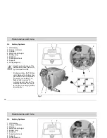
General
Before proceeding to mainte-
nance and care work you are
advised to read and comply
with the Safety Information
chapter!
Compliance with the recommended
maintenance works will give you the
certitude of always having a reliable
machine at disposition.
Daily or weekly maintenance and repair
works may be executed by the driver/
operator having been trained accordin-
gly. Further Hako system maintenance
works have to be executed by qualified
personnel only. Please contact your lo-
cal Hako Service Centre or Hako con-
tract dealer. We cannot be held liable
for damages resulting from non-com-
pliance with these instructions.
Please indicate the machine's serial
number with any enquiry or spare part
order, see paragraph 1.7 - Nameplate.
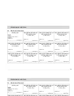
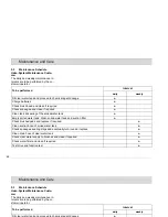
5.1
Hako System Maintenance
The Hako System Maintenance:
• guarantees reliable operability of the
Hako machines (preventive mainte-
nance)
• minimizes operating costs, repair
costs and maintenance costs
• ensures long service life and opera-
bility of the machine
The Hako System Maintenance is
structured in separate modules and de-
termines specific technical works to be
executed as well as the intervals for
such maintenance works. For any spe-
cific maintenance type, the replacement
parts are determined and listed in spare
part kits.
Hako System Maintenance K:
To be performed by the customer in ac-
cordance to the maintenance and care
instructions contained in the operating
instructions (daily or weekly). The
driver/operator will be instructed upon
delivery of the machine.
Hako-System Maintenance I :
(every 125 hours of operation)
To be performed by qualified personnel
of authorised Hako Service Centre in
accordance with the machine-specific
system maintenance including spare
part kit.
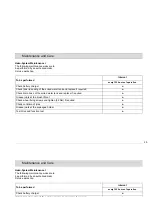
Hako-System Maintenance II:
(every 250 hours of operation)
To be performed by qualified personnel
of authorised Hako Service Centre in
accordance with the machine-specific
system maintenance including spare
part kit.
Hako-System Maintenance S:
(every 500 hours of operation safety
check)
To be performed by qualified personnel
of authorised Hako Service Centre in
accordance with the machine-specific
system maintenance including spare
part kit. Execution of all safety-relevant
inspections according to UVV-BGV-
TÜV-VDE as prescribed by law.
22
Maintenance and Care
5
Maintenance and Care
General
Before proceeding to mainte-
nance and care work you are
advised to read and comply
with the Safety Information
chapter!
Compliance with the recommended
maintenance works will give you the
certitude of always having a reliable
machine at disposition.
Daily or weekly maintenance and repair
works may be executed by the driver/
operator having been trained accordin-
gly. Further Hako system maintenance
works have to be executed by qualified
personnel only. Please contact your lo-
cal Hako Service Centre or Hako con-
tract dealer. We cannot be held liable
for damages resulting from non-com-
pliance with these instructions.
Please indicate the machine's serial
number with any enquiry or spare part
order, see paragraph 1.7 - Nameplate.
5.1
Hako System Maintenance
The Hako System Maintenance:
• guarantees reliable operability of the
Hako machines (preventive mainte-
nance)
• minimizes operating costs, repair
costs and maintenance costs
• ensures long service life and opera-
bility of the machine
The Hako System Maintenance is
structured in separate modules and de-
termines specific technical works to be
executed as well as the intervals for
such maintenance works. For any spe-
cific maintenance type, the replacement
parts are determined and listed in spare
part kits.
Hako System Maintenance K:
To be performed by the customer in ac-
cordance to the maintenance and care
instructions contained in the operating
instructions (daily or weekly). The
driver/operator will be instructed upon
delivery of the machine.
Hako-System Maintenance I :
(every 125 hours of operation)
To be performed by qualified personnel
of authorised Hako Service Centre in
accordance with the machine-specific
system maintenance including spare
part kit.
Hako-System Maintenance II:
(every 250 hours of operation)
To be performed by qualified personnel
of authorised Hako Service Centre in
accordance with the machine-specific
system maintenance including spare
part kit.
Hako-System Maintenance S:
(every 500 hours of operation safety
check)
To be performed by qualified personnel
of authorised Hako Service Centre in
accordance with the machine-specific
system maintenance including spare
part kit. Execution of all safety-relevant
inspections according to UVV-BGV-
TÜV-VDE as prescribed by law.


