


Folie 103
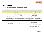
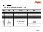
9. Drive
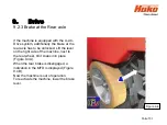
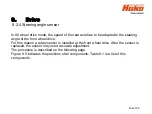
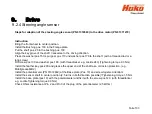
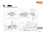
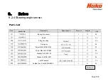
9.2.4 Steering angle sensor
Steps for adaption of the steering angle sensor (PN 01372660) to the drive motor (PN 01371270)
Instruction
Bring the front wheel to center position.
Install the Bushing pos. 100 in the Flange plate.
Put the shaft pos. 20 in the bushing pos. 100.
Align the key grove of the shaft transverse to the driving direction.
Press the washer pos.150; spur gear pos.110 und washer pos.170 to the shaft. (with a threaded rod or a
long screw)
Fit Screw pos.130 and washer pos.180. (with threadlocker
e.g. Loctite 243) (Tightening torque 9.3 Nm)
Install the feather key pos.200 and grease the upper end of the shaft as a corrosion protection. (e.g.
Mobilgrease MB2 )
Install the potentiometer (PN 01372660) at the Base plate (Pos. 10) and screw togeter. Attention!
Install the sensor shaft in center position (2.5 turns in both direction possible)! Tighetening torque 1,5 Nm.
Install the base plate (pos.10) with the potentiometer and fix it with the screw pos.120. (with threadlocker
e.g. Loctite Tightening torque 9.3 Nm)
Check Ohms resistance at Pin 2 and Pin 3 of the plug of the potentiometer (2,5 kOhm)
Summary of Contents for Scrubmaster B175 R
Page 37: ...3 Technical Data Sheet 37...
Page 38: ...3 Technical Data Sheet 38...
Page 39: ...3 Technical Data Sheet 39...
Page 40: ...3 Technical Data Sheet 40...
Page 41: ...3 Technical Data Sheet 41...
Page 42: ...3 Technical Data Sheet 42...
Page 43: ...3 Technical Data Sheet 43...
Page 44: ...3 Technical Data Sheet 44...
Page 46: ...4 1 Hako System Maintenance customer Sheet 46...
Page 47: ...4 1 Hako System Maintenance customer Sheet 47...
Page 48: ...4 2 Hako System Maintenance I Sheet 48...
Page 49: ...4 2 Hako System Maintenance I Sheet 49...
Page 50: ...4 2 Hako System Maintenance I Sheet 50...
Page 51: ...4 3 Hako System Maintenance II Sheet 51...
Page 52: ...4 4 Hako System Maintenance III S Safety Check Sheet 52...
Page 65: ...6 Machine settings 6 1 6 Charging characteristics for integrated charger Sheet 65...
Page 74: ...7 Mechanical components Figure 7 2a Figure 7 2b Sheet 74 7 1 Squeegee...
Page 76: ...7 Mechanical components Height adjustment Figure 7 4 Sheet 76 7 1 Squeegee...
Page 104: ...9 Drive 9 2 4 Steering angle sensor Figure 9 5 180 130 170 150 120 Folie 104...
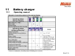
Page 113: ...11 Battery charger 11 1 Operating manual Sheet 113...
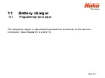
Page 114: ...11 Battery charger Sheet 114 11 1 Operating manual...
Page 115: ...11 Battery charger Sheet 115 11 1 Operating manual...
Page 116: ...11 Battery charger Sheet 116 11 1 Operating manual...
Page 123: ...13 Notes Sheet 123...
Page 124: ...Sheet 124 13 Notes...


